Arduino IDE
Installation
First, you need to install the Arduino IDE on your PC. There are 2 different versions:
- Arduino IDE 2.X.X.
- Legacy IDE (1.8.X).
Both can be used with the same functionality, but we recommend the latest Arduino IDE 2 version. It can be downloaded at https://www.arduino.cc/en/software. Download the version according to your operating system and follow the steps to complete the install.
Make sure that the installed IDE version is at least 1.8.13 or above.
Boards package
After the IDE is properly installed in the OS, install the Industrial Shields boards package, which provides the support for our PLCs needs to be installed.
To do so, follow the steps:
- Open the IDE, and on the top left corner, select: File > Preferences.
- Scroll down until you see the Additional boards manager URLs field. Insert the following link in it:
http://apps.industrialshields.com/main/arduino/boards/package_industrialshields_index.json
- Close the menu pressing the Ok button.
- On the top left corner, select: Tools > Board > Boards manager.
- Use the search bar to look for the "industrialshields-avr" package and install the latest available version.
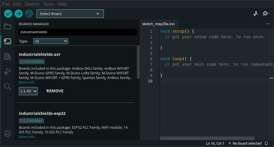
- Close the boards manager by clicking the icon on the left bar.
With these simple steps the boards package is already installed, and the environment ready to program the PLC.
PLC Programming
Let's see how to program the PLC for the first time. Before doing so, the IDE needs to be configured with the board model being used. In this example, we will use an M-Duino 21+. To do so, follow the steps:
- Power the PLC with a 12-24Vdc power supply.
- Connect the PLC to the PC using a USB cable.
- Select the family: on the top left corner, select Tools > Board > Industrial Shields AVR Boards > M-Duino Family.
- Choose the PLC variant: select Tools > Board > Model > M-Duino 21+
- In Tools > Port, select the USB port corresponding to the PLC, for example /dev/ttyACM0 or COM3 (the nomenclature differs depending on the operating system).
At this point the program can be uploaded to the PLC. Let's use an example one to see how it is done: go to File > Examples > RTC > RTC. This example, included with the libraries, gets the time from the RTC chip and sends it through the serial port.
On the top left corner of the IDE there are 2 buttons, a tick and an arrow, used to compile and upload the program, respectively. Go ahead and press the upload button, which will automatically compile the program and upload it to the PLC. When the upload is completed, a message will appear on the right bottom corner.

Finally, the serial monitor can be used to see what the PLC is outputting through the serial port. To open it, press the "Serial Monitor" button located on the top right corner of the IDE. A new tab will open in place of the console with the monitor, with a few options that can be configured. In this case, change the baud rate according to the one being used by the PLC, 9600 (the baud rate is set in the PLC program).
The output of this example program is the time measured by the RTC:

There are no comments for now.
to be the first to leave a comment.