DALI
DALI (Digital Addressable Lighting Interface) is a communication protocol used in smart lighting systems for precise control and automation of lighting networks. It allows individual lights or groups of lights to be addressed and managed independently, enabling features such as dimming, color changes, and scheduling.
DALI is an optional communication. Only the M-Duino and Ardbox PLCs with the additional communication board can use it.
Hardware
The Arduino based PLC with DALI feature 1 DALI bus, capable of controlling up to 64 devices. In order to use it, the only requirement is to connect the DA+ and DA- pins need to the bus, this way:
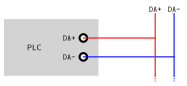
Connect the PLC and the other DALI devices in one bus, and you can start using DALI. Depending on the PLC model, the Arduino pins used are:
- M-Duino: 18 and 19.
- Ardbox: 14 and 16.
Remember to properly power the PLC with a 12-24V power supply.
Software
To use the DALI communication, the proper PLC model needs to be selected in the IDE. Go to Tools > Board > Industrial Shields AVR Boards, and select M-Duino DALI Family or Ardbox DALI Family, according to the PLC model.
Once the model is properly selected, the PLC can be programmed. A DALI library is included with the Industrial Shields boards package, names "Arduino DALI library", which is used to communicate using DALI.
For example, let' see how the library is sued with the DataQueries example:
- Find the example in the IDE, located in File > Examples > Arduino DALI library > DataQueries.
- Define your lamp address at #define LAMP_ADDR 0.
- Initialize the dali object instantiating the pins where the DALI bus is connected. As explained, on the hardware section of this page, these are different in each PLC Model:
- For Ardbox Family (pins 14 and 16): DALI dali(14, 16);
- For M-Duino Family (pins 18 and 19): DALI dali(18, 19);
- Once the DALI pins are properly set, program the PLC.
This program controls a DALI lamp, toggling its intensity between off and a set value (175). It initializes the DALI interface, sets the lamp intensity, checks and prints the lamp's state and intensity to the serial monitor, and toggles the intensity every 2 seconds. If there are discrepancies between the desired and actual states or intensity values, it prints error messages for debugging.
For more information about this topic, check the following posts:
There are no comments for now.
to be the first to leave a comment.