RS232
RS232 is a standard for serial communication that has been widely used for connecting computers and peripheral devices. This point-to-point communication standard operates through a defined set of electrical characteristics and signal functions, allowing the transmission of data one bit at a time along a single data line.
While its simplicity and reliability have made it a longstanding choice in many applications, RS-232 is typically limited to short distances and low speeds. In addition, it is designed to allow the transmission of data between a DTE (data terminal equipment) and a DCE (data communication equipment), which means it only support communication between 2 devices at a time.
The Arduino based Industrial Shields PLCs feature RS232 communication, leveraging an RS232 transceiver (the MAX232) and a serial port of the Arduino in the PLC. As such, the RS232 usage is really similar to the one of common Serial TTL ports.
Hardware
RS232 uses unbalanced (single-ended) signaling: data is transmitted in the form of voltage levels over a single wire relative to a common ground. Therefore, it uses 2 cables to achieve full-duplex communication, TX and RX, and it requires a common ground between the devices.
The connections between devices are:
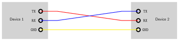
Depending on the PLC, the steps needed to configure the RS232 are different. Follow the procedure according to your PLC model:
Depending on the configuration, the Ardbox can use RS232 through a hardware serial interface of the Arduino or through software serial. The primary option would be using hardware serial, but in case it is already being used (for example, for RS485), software serial is the alternative. Regarding hardware, there are some jumpers and switches that need to be configured.
Jumpers
The Ardbox Analog PLCs have 2 set of jumpers, which can be accessed by removing the cover of the device.
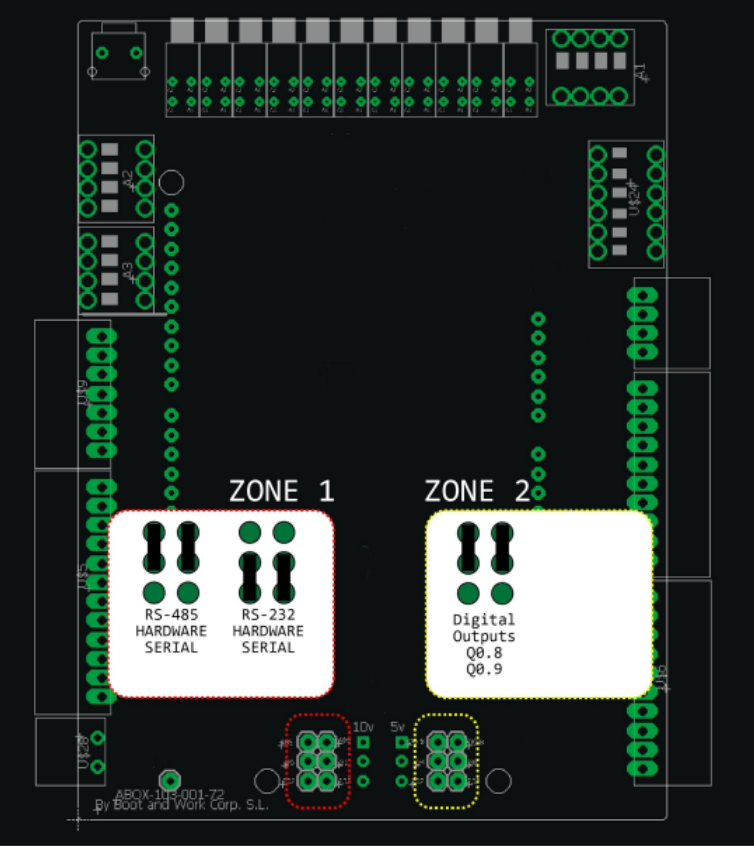
Zone 1 Pins | |
Left | Right |
RS485 | RS485 |
D0 (Arduino) | D1 (Arduino) |
RS232 | RS232 |
Zone 2 Pins | |
Left | Right |
Q0.9 | Q0.8 |
D4 (Arduino) | D8 (Arduino) |
RS232 (software serial) | RS232 (software serial) |
Hardware serial
In order to use the hardware serial, place the jumpers in zone 1 according to the previous image: connecting the pins in the middle row with the ones in the lower row.
Software serial
To use software serial, the jumpers in zone 1 need to be connected to RS485, and the zone 2 jumpers need to be placed in the lower position: connecting the pins in the middle row with the ones in the lower row.
DIP Switches
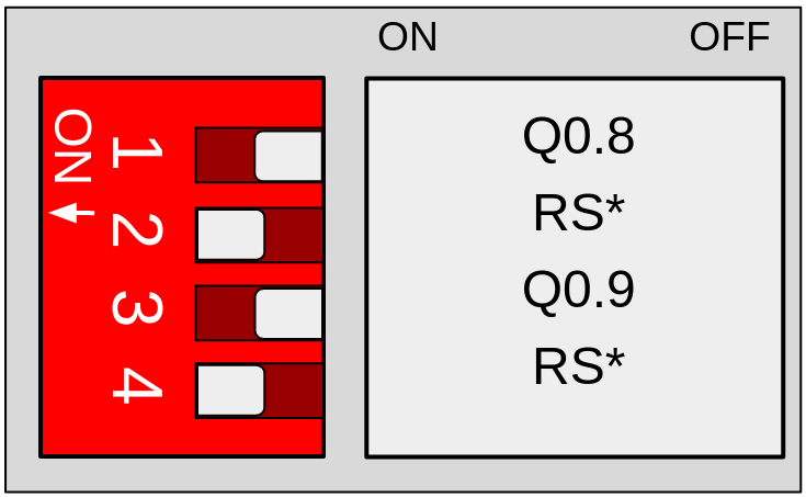
Finally, there are some switches that need to be configured only when using hardware serial. Look for the switches located on the top side of the PLC (next to LEDs) and configure them the following way:
- Switch 1 to OFF to enable RS-232.
- Switch 2 to ON to enable RS-232
- Switch 3 to OFF to enable RS-232.
- Switch 4 to ON to enable RS-232.
Depending on the configuration, the Ardbox can use RS232 through a hardware serial interface of the Arduino or through software serial. The primary option would be using hardware serial, but in case it is already being used (for example, for RS485), software serial is the alternative. Regarding hardware, there are some jumpers and switches that need to be configured.
Jumpers
The Ardbox Analog PLCs have 3 set of jumpers, which can be accessed by removing the cover of the device.
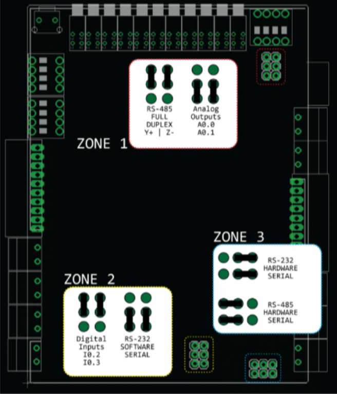
Zone 1 Pins | |
Left | Right |
RS485 Y+ | RS485 Z- |
Enable | Enable |
A0.0 | A0.1 |
Zone 2 Pins | |
Left | Right |
I0.2 | I0.3 |
D4 (Arduino) | D8 (Arduino) |
RS232 (SS) | RS232 (SS) |
Zone 3 Pins | |
Left | Right |
RS485 | RS485 |
D0 (Arduino) | D1 (Arduino) |
RS232 | RS232 |
Hardware serial
In order to use the hardware serial, place the jumpers in zone 3 according to the previous image: connecting the pins in the middle row with the ones in the lower row.
Software serial
To use software serial, the jumpers in zone 3 need to be connected to RS485, and the zone 2 jumpers need to be placed in the lower position: connecting the pins in the middle row with the ones in the lower row.
DIP Switches
Finally, there are some switches that need to be configured only when using hardware serial. Look for the switches located on the top side of the PLC (next to LEDs) and configure them the following way.
- Switch 1 to ON to enable RS-232.
- Switch 2 to OFF to enable RS-232
- Switch 3 to ON to enable RS-232.
- Switch 4 to OFF to enable RS-232.
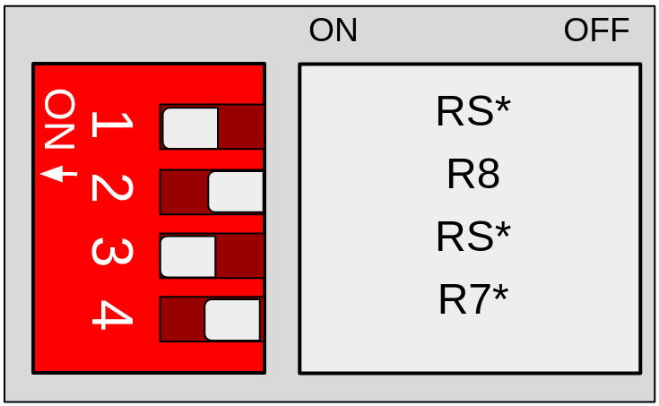
Remember to properly power the PLC with a 12-24V power supply.
Software
The industrialshields boards package includes an RS232 library to make programming easier. This library is used as the Arduino Serial library, with methods such as available(), read(), write(), etc.
The following example establishes a RS232 communication and allows the user to read or send messages from the terminal of the PC:
API Reference
Description:
Initializes the communication with specified baud rate and serial configuration. Must be called before any other communication functions.
Syntax:
RS232.begin(baudrate, config);
Parameters:
- RS232: The RS232 object.
- baudrate: The baud rate for the communication.
- config: The serial configuration (data bits, parity, and stop bits). Default is SERIAL_8N1 (8 data bits, no parity, 1 stop bit).
Returns:
Nothing.
Description:
Checks if there are any bytes available to read from the RS232 buffer.
Syntax:
RS232.available();
Parameters:
- RS232: The RS232 object.
Returns:
Returns the number of bytes available to read.
Description:
Reads a byte from the RS232 buffer.
Syntax:
RS232.read();
Parameters:
- RS232: The RS232 object.
Returns:
Returns the byte read from the RS232 buffer, or -1 if no data is available.
Description:
Writes a byte or a buffer of bytes to the RS232 bus.
Syntax:
RS232.write(value);
RS232.write(buff, len);
Parameters:
- RS232: The RS232 object.
- value: The byte to be transmitted over RS232.
- buff: A pointer to the buffer of bytes to be transmitted.
- len: The number of bytes to transmit from the buffer.
Returns:
Returns the number of bytes written.
There are no comments for now.
to be the first to leave a comment.