Inputs/Outputs
Inputs
Digital inputs are used to capture signals that exist in one of two states: high or low. Industrial Shields Arduino PLCs interpret as high values of 5 Vdc or higher, up to 24 Vdc, whereas values lower than 5V are interpreted as low. There are 2 types of inputs which can be used as digital input:
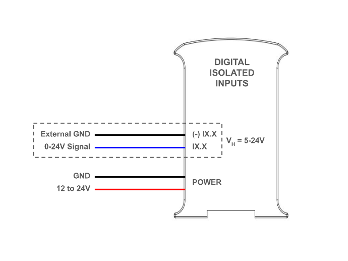
- Digital isolated inputs (5 - 24 Vdc): these inputs are opto-isolated, which means they have an extra protection and they use an external ground pin for reference.
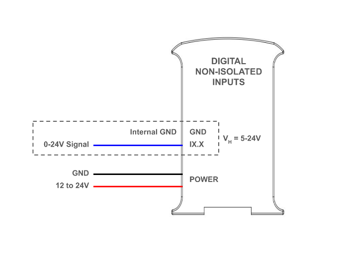
- Digital non-isolated input (5 - 24 Vdc): these inputs are not opto-isolated, and they use the internal GND of the PLC as reference.
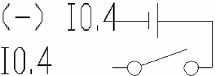
The type of an input can be identified by the serigraphy on the PLC. In order to use them, the following diagrams illustrate the necessary connections for each of the inputs.
5V - 24V isolated input

5V - 24V non-isolated input
Software
Program usage
The digital inputs are used like a regular Arduino pin. In order to read their value, use the "digitalRead()" function, with the input name as its parameter. Notice that all inputs on Industrial Shields PLC are named in the same format: I0.0, I0.1, I1.2, etc. These inputs can be accessed directly on the program by replacing the dot with an underscore: I0_0, I0_1, I0_2.
The following example illustrates how to read input I0.0 and send the value through the serial port:
API reference
Description:
Reads the value from a specified digital input, either HIGH or LOW.
Syntax:
digitalRead(input)
Parameters:
- input: the digital input you want to read, which can be a PLC input (e. g. I0_0) or an Arduino pin.
Returns:
HIGH or LOW
Analog input provides a way to read analog voltage levels, coding the value with an N-bit number.
- Voltage range: from 0 to 10 Vdc.
- Resolution: 10 bits, which means the read values can range between 0 and 1023.
Additionally, the analog inputs can also be used as non isolated digital inputs tolerating up to 24Vdc. To do so, refer to the digital inputs section. The analog inputs are the ones between IX.7 and IX.12, with X being 0, 1 or 2 depending on the zone.
0V - 10Vdc Analog input
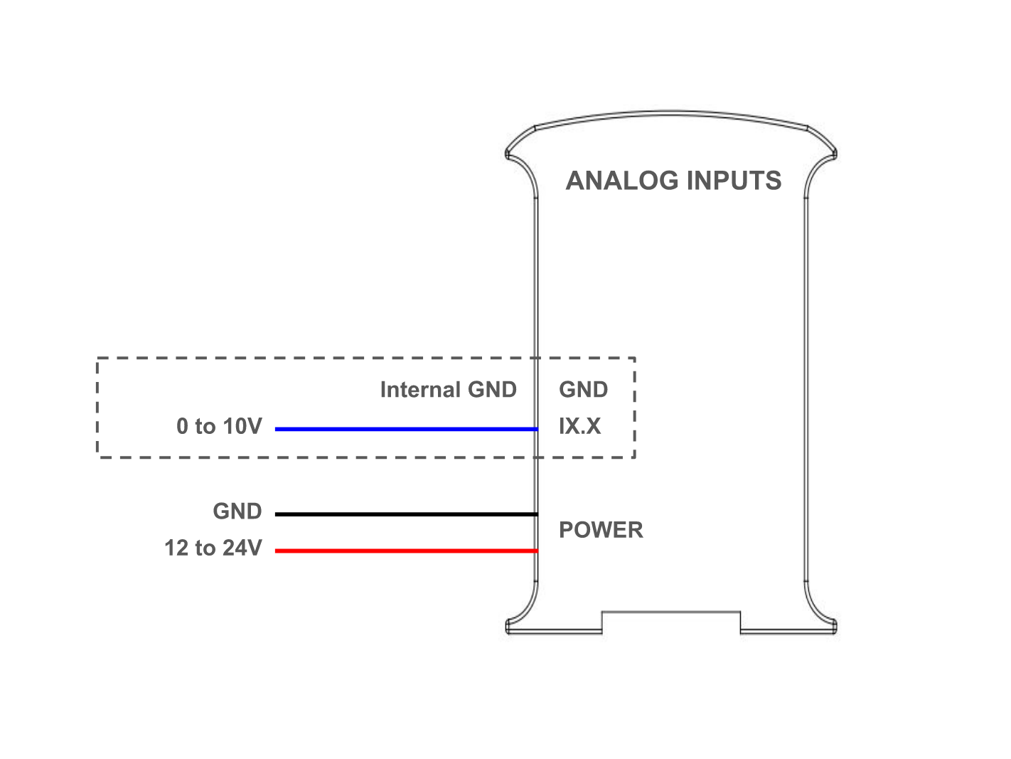
Software
Program usage
The analog inputs are used like a regular Arduino pin. In order to read their value, use the "analogRead()" function, with the input name as its parameter. Notice that all inputs on Industrial Shields PLC are named in the same format: I0.7, I0.8, I1.7, etc. These inputs can be accessed directly on the program by replacing the dot with an underscore: I0_7, I0_8, I1_7.
The following example illustrates how to read input I0.7 and send the value through the serial port:
API reference
Description:
Reads the value from the specified analog input. Arduino based PLCs contain a multichannel, 10-bit analog to digital converter. This means that it will map input voltages between 0 and the10V into integer values between 0 and 1023.
Syntax:
analogRead(input)
Parameters:
- input: the analog input you want to read, which can be a PLC input (e. g. I0_7) or an Arduino pin.
Returns:
The analog reading on the pin (0-1023). Data type: int.
Some of the digital inputs in the Arduino based PLCs are interrupt capable, which means they can be used with ISRs (interrupt service routine) to trigger certain code execution when an event (a change of state in the pin) is detected. The interrupt capable pins are different on each PLC. They need to be connected the same way as the digital inputs, check out the corresponding section to see how.
Available interrupt inputs
PLC Model | Interrupt Inputs* |
M-Duino Analog | I0.5, I0.6, I1.5, I1.6, I2.5, I2.6 |
M-Duino Relay | I0.0, I0.1, I1.0, I1.1, I2.0, I2.1 |
Ardbox Analog | I0.0 |
Analog Relay | I0.0 |
* Some PLC Variants with expansion modules such as GPRS might lose some of the interrupt pins.
Switch configuration
Interrupt inputs usually share a pin with another functionality, which means that when they are used, the other functionality will not be available. The interrupts are activated using a DIP switch on the PLC. These are the switches for each model and input:
- M-Duino Analog:
- I0.5 and I0.6 also work as Pin3 and Pin2. Enable Interrupts turning ON the bottom switches number 3 and 4 of the communication switches.
- I1.5 and I1.6 also work as Tx1 and Rx1. Enable Interrupts turning ON the top switches number 1 and 2 of the communication switches.
- I2.0 and I2.1 also work as SDA and SCL. Enable Interrupts turning ON the top switches number 3 and 4 of the communication switches. Keep in mind that In this case you won’t be able to use I2C.
- M-Duino Relay:
- I0.0 and I0.1 also work as Pin3 and Pin2. Enable Interrupts turning ON the bottom switches number 3 and 4 of the communication switches.
- I1.0 and I1.1 also work as Tx1 and Rx1. Enable Interrupts turning ON the top switches number 1 and 2 of the communication switches.
- I2.0 and I2.1 also work as SDA and SCL. Enable Interrupts turning ON the top switches number 3 and 4 of the communication switches. Keep in mind that In this case you won’t be able to use I2C.
- Ardbox Analog/Relay:
- I0.0 also works as SDA-D2/I0.0. Enable interrupts turning ON the top switch number 4.
- I0.0 also works as SDA-D2/I0.0. Enable interrupts turning ON the top switch number 4.
For more information about each PLC model switches, check its user guide.
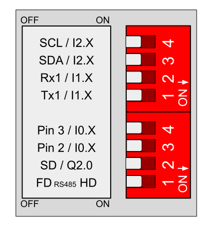
M-Duino Analog/Relay switches
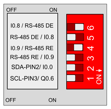
Ardbox Analog switches
Ardbox Relay switches
Software
Program usage
The usage of the interrupt pins works the same way as an Arduino board: the "attachInterrupt()" function is used to configure the interrupt with a pin, function and type of activation. The following example shows how to use the interrupt pins. In this case, the function "isrI0_5()" is automatically called every time a change of state occurs on the I0.5 pin.
API reference
Description:
Attaches an interrupt to a pin, specifying the method of activation of the interrupt and a function (ISR), which will be executed when the interrupt is triggered.
Syntax:
attachInterrupt(digitalPinToInterrupt(pin), ISR, mode)
Parameters:
- pin: the interrupt input of the PLC or the Arduino pin number.
- ISR: the ISR to call when the interrupt occurs; this function must take no parameters and return nothing. This function is sometimes referred to as an interrupt service routine.
- mode: defines when the interrupt should be triggered. Four constants are predefined as valid values:
- LOW to trigger the interrupt whenever the pin is low.
- CHANGE to trigger the interrupt whenever the pin changes value.
- RISING to trigger when the pin goes from low to high.
- FALLING for when the pin goes from high to low.
Returns:
Nothing
Outputs
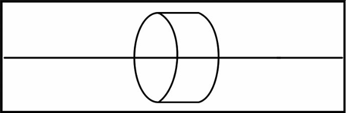
The Arduino based PLCs are equipped with PNP digital outputs, capable of providing digital signals between 0Vdc and up to 24Vdc. These outputs are labeled as QX.X, and can be identified with the next symbol.
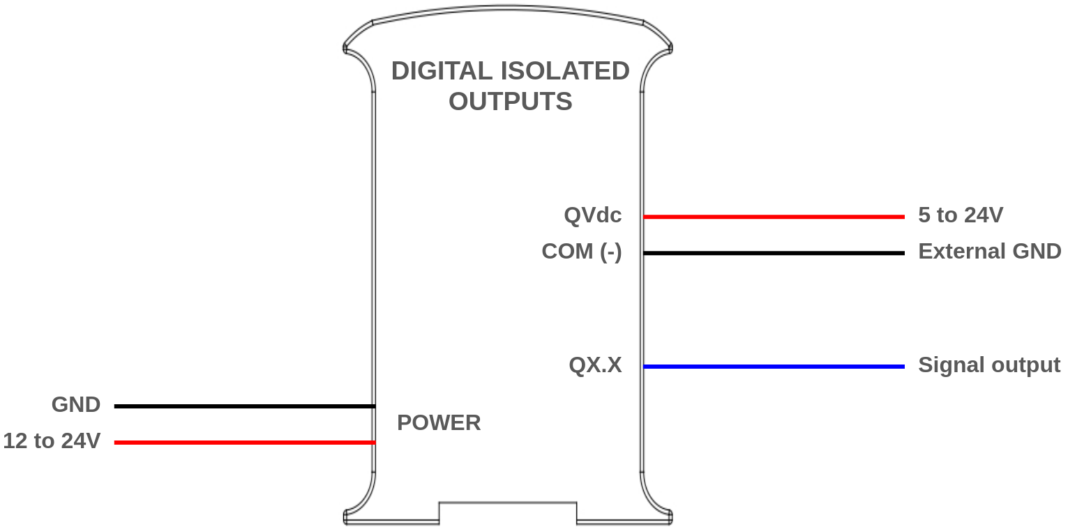
The highest output value for the digital outputs in the Arduino PLCs is 24Vdc, but it needs to be configured between 5Vdc and 24Vdc. To do so, use the two pins located next to the outputs: QVdc and COM(-). For instance, should you want to set the output to 24V, the QVdc pin should be connected to 24V and the COM(-) pin to GND. The following diagram illustrates an example connection:
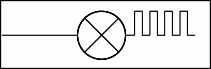
Digital output (PWM optional)
Software
Program usage
The digital outputs are used like a regular Arduino pin. In order to write their value, use the "digitalWrite()" function, with the output name and value as its parameters. Notice that all digital outputs on Industrial Shields PLC are named in the same format: Q0.0, Q0.1, Q1.2, etc. These outputs can be accessed directly on the program by replacing the dot with an underscore: Q0_0, Q0_1, Q0_2.
The following example illustrates how to alternate the value of an output between LOW and HIGH each second:
API reference
Description:
Write a HIGH or a LOW value to a digital output.
Syntax:
digitalWrite(output, value)
Parameters:
- output: the you want to use, which can be a PLC output (e. g. Q0_2) or an Arduino pin.
- value: HIGH or LOW.
Returns:
Nothing.
Some of the digital outputs in both the M-Duino and Ardbox PLCs are PWM capable, so they can be used to generate a PWM signal of varying frequencies. They can be identified on the PLC with the following symbol.
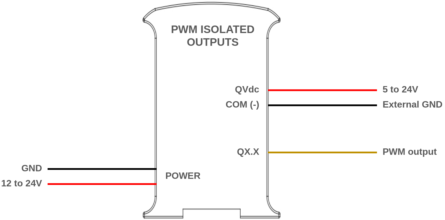
The PWM outputs can work with the same voltages as the digital outputs, also being configured with the QVdc and COM(-) pins (refer to the digital outputs section for more information). The next diagram illustrates the necessary connections to use them.
PWM capable output
Software
Program usage
A PWM of various frequencies can be generated using the timer peripheral in the AVR architecture chips. To do this, download and install our avr-Pulses library, which takes care of the timers configuration.
There are some things to keep in mind when using this library:
- On an Arduino, each timer is associated with some pins. Only pins with a timer can output a pulse using this method, and if two pins share the same timer, they cannot work at different frequencies. Check the GitHub to see the information about the Arduino PLC pins.
- Some pins use TIMER0. When the TIMER0 pins are used, all the time functions lose their time reference and do not work properly, such as "delay()", "millis()", "micros()" , "delayMicroseconds()" and others.
Check the following program example where a 500Hz pulse is configured:
API reference
Description:
Start a train of pulses in the Arduino pin at the specified frequency. Depending on the frequency, a correct precision setting must be set. Check the table in the parameter description.
Syntax:
startPulses(pin, freq, precision)
Parameters:
- pin: the PWM output you want to use, which can be a PLC output (e. g. Q0_1) or an Arduino pin.
- freq: the frequency of the resulting PWM, in Hz.
- precision: value between 1 and 5 to configure the timer used in the generated pulse.
- Precision = 1: from 30Hz to 150Hz
- Precision = 2: from 150Hz to 500Hz
- Precision = 3: from 500Hz to 4kHz
- Precision = 4: from 4kHz to 32kHz
- Precision = 5: from 32kHz to 4MHz
Returns:
Nothing.
Description:
Stop the train of pulses running in the specified output.
Syntax:
stopPulses(pin)
Parameters:
- pin: the output whose pulse you want to stop, which can be a PLC output (e. g. Q0_0) or an Arduino pin.
Returns:
Nothing.
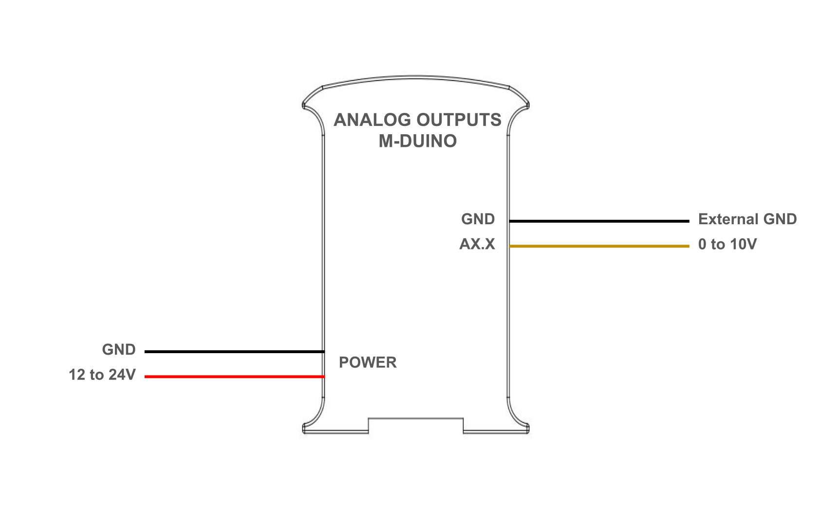
The analog outputs provide a voltage signal determined by a digital value with an N-bit number.
- Voltage range: from 0 to 10 Vdc.
- Resolution: 8 bits.
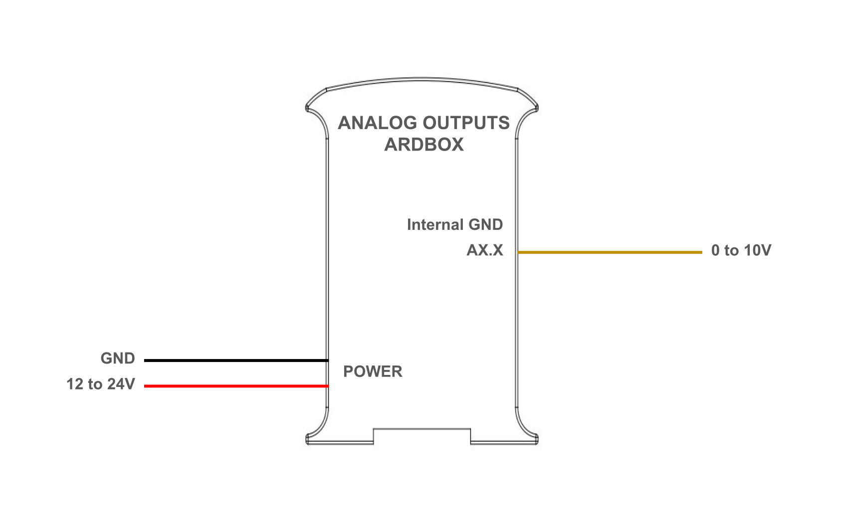
The analog outputs are labeled as AX.X, and must be properly activated using the DIP switches in each PLC. For example, to use A0.1 there is a switch to choose between A0.1 and Q0.1, where A0.1 should be chosen.
In the case of the Ardbox PLC, the analog outputs use the internal ground of the PLC as reference, whereas the M-Duino PLC has an external pin to set the ground reference.
Analog output
Software
Program usage
The analog outputs can be used with the "analogWrite()" function. This function, working the same way as it does on regular Arduino boards, outputs a PWM. A low-pass filter is used to convert the PWM signal to an analog voltage, which means the voltage can be controlled by varying the duty cycle of the PWM signal:
- 0 results in a 0% duty cycle and 0V.
- 255 results in a 100% duty cycle and 10V.
The following example illustrates how to set the output voltage of the A0.5 output:
API reference
Description:
Writes an analog value to an output. The analog signal is achieved by generating a PWM wave and filtering it with a low-pass filter. To determine the value of the output, the duty cycle of the PWM is defined using an 8 bit value:
- 0: 0% duty cycle, 0V.
- 255: 100% duty cycle, 10V.
Syntax:
analogWrite(output, value)
Parameters:
- output: the analog output you want to use, which can be a PLC output (e. g. A0_1) or an Arduino pin.
- value: the duty cycle: between 0 (0V) and 255 (10V).
Returns:
Nothing.
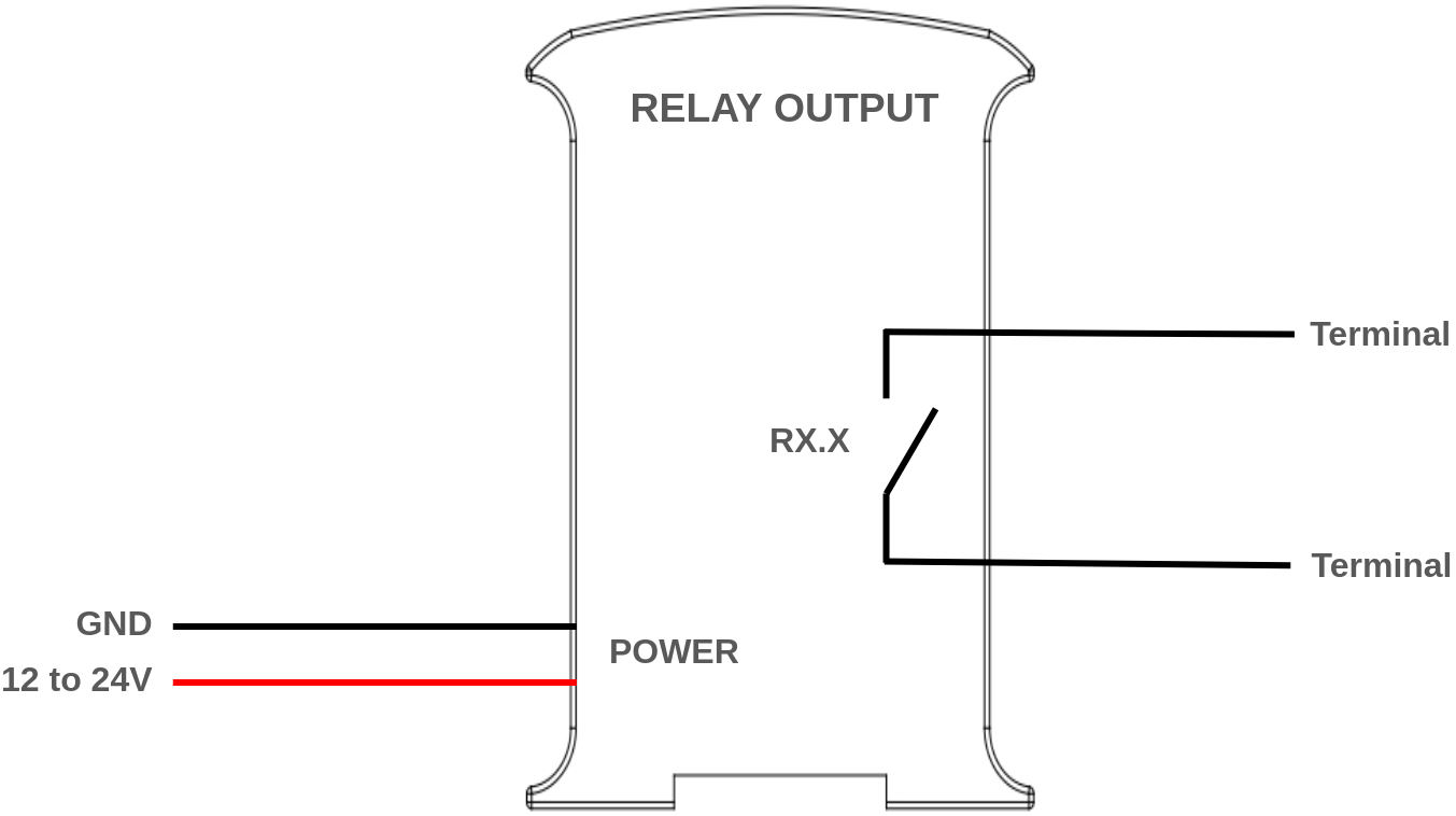
A relay is an electromagnetic switch controlled by an electric signal. Some variants of the Industrial Shields PLCs based on Arduino include relay outputs, which can be used for control applications.
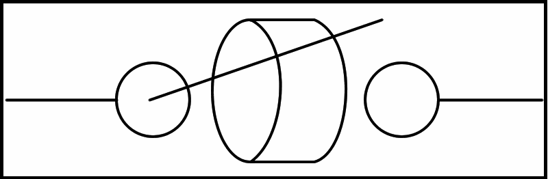
The terminals of each relay can be identified by the serigraphy of the PLC. Each relay has its 2 terminals exposed, with no polarity. Normally, the state of the relays is open, and they close when they are activated.
The relays used in Industrial Shields PLCs are rated for:
- Up to 5A at 250Vac.
- Up to 3A at 30Vdc.

Relay
Software
Program usage
The relays are controlled by a digital pin inside the PLC, so they are controlled in the same way as the digital outputs. Using the "digitalWrite()" function, the relays can be activated or deactivated (closed or opened, respectively):
- Set the output to LOW to open the relay.
- Set the output to HIGH to close the relay.
For example, the following code opens and closes relay R0.1 every 1 second.
API reference
Description:
Write a HIGH or a LOW value to the pin controlling a relay:
- LOW to open the relay.
- HIGH to close the relay.
Syntax:
digitalWrite(output, value)
Parameters:
- output: the relay you want to use, which can be a PLC output (e. g. R1) or an Arduino pin.
- value: HIGH or LOW.
Returns:
Nothing.
Arduino pins
The Ardbox and M-Duino series PLCs expose some of the pins of the Arduino inside them. As the Arduino pins, they can be used as input or output, and their operating voltage is 5V.
As these pins are directly connected to the Arduino Leonardo/MEGA inside the Ardbox/M-Duino PLCs, you need to be careful when using them. Do not surpass the operating voltage of 5V or the Arduino board could be damaged.
There is not any circuitry between the Arduino inside the PLC and these pins, so they can be used in the same ways as a regular Arduino board pin. For example:
- Use them as slave select for SPI devices.
- Interface with OneWire devices, such as the DS18B20 temperature probe.
The pins available for each PLC model are the following:
PLC | Pins |
Ardbox | 2*, 3* |
M-Duino | 2, 3 |
*Pins 2 and 3 in the Ardbox, which can be used for I2C as well, need to be activated using the corresponding switches that you can see above.
Usage
These pins can be used with the regular Arduino functions: pinMode(), digitalRead() and digitalWrite(), as well as other libraries that make use of them, such as the OneWire library.
Check out the Arduino Digital Pins documentation page for more detailed info about this topic.
There are no comments for now.
to be the first to leave a comment.