Technical Features
Raspberry PLC Family
Initial installation
Getting started
First of all, the Raspberry Pi PLC will need an operative system to start running. Although you can use any GNU/Linux distribution, we recommend you to stick into Raspberry Pi OS, which is the official supported OS for the Raspberry board.
To install an OS onto the Raspberry Pi, please refer this guide.
If you have followed the guide accurately, you can access the Raspberry PLC either through a screen and keyboard or via SSH using the Ethernet port. In case you prefer the latter method, you can follow this guide on how to access the PLC via SSH.
Programming the PLC
The primary benefit of using the Raspberry Pi PLC is that it is compatible with any Integrated Development Environment (IDE) that works with the compatible programming languages. This can be accomplished by either accessing an IDE installed on the PLC via X-forwarding through "ssh -X", or using an IDE installed on your computer, and then transferring the files through SFTP/FTP.
Although a variety of programming languages can be used, we advise utilizing Python, C++, and Node-RED as these are our officially supported languages.
Python
Python 3.9.2 is already pre-installed in the Raspberry Pi OS, and therefore, doesn't require any additional installation.
However, to access the PLC's Input/Output (I/O) and interrupts, you will need to install both the rpiplc and rpiplc-python3 libraries, which should already be installed if you followed the guide to install the OS.
- Install C++ library for Raspberry Pi PLC (dependency for the Python library): rpiplc-library Installation guide
- Install Python library for Raspberry PLC: rpiplc-python3-library Installation guide
C++
The GCC toolchain is pre-installed with the Raspberry Pi OS. Therefore, there is no need for any additional installation to use C++.
However, to utilize the PLC's I/O and interrupts, you will require the rpiplc libraries, which should already be installed if you followed the guide to install the OS.
- Install C++ library for Raspberry Pi PLC (dependency for the Python library): rpiplc-library Installation guide
Node-RED
Node-RED is a browser-based flow editor that enables the graphical programming of hardware devices, APIs, and online services. It is constructed on top of Node.js, which allows for the full use of its event-driven, non-blocking model.
Unlike Python or C++, Node-RED must be manually installed. To do so, you can either follow the last step of the OS installation guide or refer to the User Guide.
Power supply
All Raspberry Pi based industrial PLC’s (programmable logic controllers) can be powered between 12-24V. The Raspberry Pi family has a consumption between -mA and +mA. So, the recommended power supply is 2A or higher. Any Industrial power supply will be a good choice to power supply them.
Our units are designed to be powered between 12-24V. Just powering them with the USB, the unit will not be able to perform their features.
If for some reason you would like to use a power supply lower that is less than 3A contact with Industrial Shields technical support to ensure that your system will complete your functionalities without any power issue.
The next diagram illustrates the necessary connections to properly power a PLC:

DIP Switches
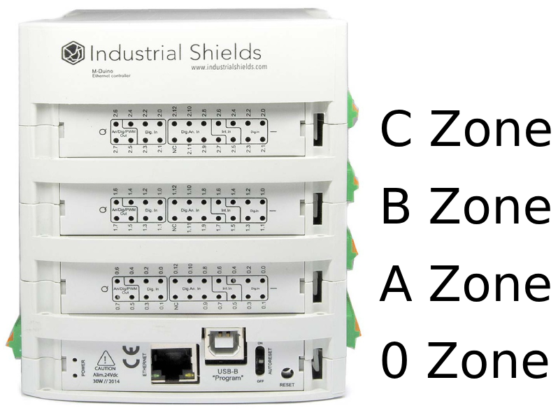
The Raspberry Pi based PLCs have some switches which can be used to configure certain functionalities of the PLC. This section explains how to use them properly. To differentiate between the different parts of the PLC and locate every switch accordingly, the following nomenclature will be used:
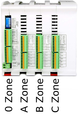
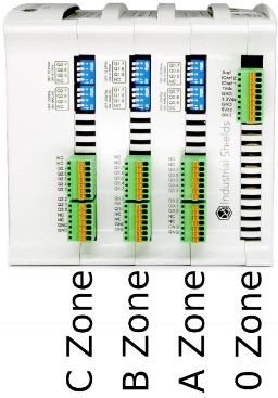
B, C and D zone: Analog switch

Switch | OFF | ON |
1 | AX.5 | QX.5 |
2 | AX.6 | QX.6 |
3 | AX.7 | QX.7 |
4 | NC | NC |
These switches are used to choose between digital or analog output, according to the previous table. If it is set to OFF, only the corresponding analog output will be available. If it is set to ON, only the corresponding digital output will be available. The switches behave the same way in zones B, C and D, with the "X" value being different depending on the zone:
- Zone B: X = 0
- Zone C: X = 1
- Zone D: X = 2
Power consumption
This report presents an analysis of the power consumption of various Raspberry PLC models under different operational scenarios. Understanding power usage is critical for optimizing efficiency and ensuring reliable performance in industrial applications. The tests conducted include scenarios such as resting, where the PLC is idle, outputs set to HIGH, representing maximum output load, and stress conditions, simulating peak operational demand. The results aim to provide valuable insights into the energy requirements of these devices in various usage scenarios.
Resting
In this scenario, the Raspberry PLC is powered on, with all pins and communications turned off and utilizing a 24V power supply. This test measures the baseline power consumption when the device is idle and not actively engaged in any processing or output tasks.
MODEL | CURRENT (mA) | POWER (W) |
| Ethernet CPU | 160 | 3,84 |
| 21+ | 150 | 3,6 |
| 42+ | 157 | 3,768 |
| 58+ | 160 | 3,84 |
| 19R+ | 155 | 3,72 |
| 38R+ | 157 | 3,768 |
| 57R+ | 180 | 4,32 |
| 38AR+ | 157 | 3,768 |
| 53ARR+ | 160 | 3,84 |
| 57AAR+ | 160 | 3,84 |
| 54ARA+ | 160 | 3,84 |
| 50RRA+ | 160 | 3,84 |
All outputs HIGH
For this test, the Raspberry PLC is configured to set all its output pins to
a high state utilizing a 24V power supply. However, the outputs are not
connected, which means that the power consumption will vary depending
on the current drawn by the device connected to each output.
MODEL | CURRENT (mA) | POWER (W) |
| Ethernet CPU | - | - |
| 21+ | 164 | 3,936 |
| 42+ | 185 | 4,44 |
| 58+ | 200 | 4,8 |
| 19R+ | 260 | 6,24 |
| 38R+ | 358 | 8,592 |
| 57R+ | 482 | 11,568 |
| 38AR+ | 267 | 6,408 |
| 53ARR+ | 375 | 9 |
| 57AAR+ | 280 | 6,72 |
| 54ARA+ | 280 | 6,72 |
| 50RRA+ | 375 | 9 |
Stress
Under stress conditions, the Raspberry PLC is subjected to intensive computational tasks or high-demand processes. This test evaluates the peak power consumption when the device is operating at its maximum capacity, providing valuable information for scenarios where the PLC is under heavy load. This test is done using the "stress --cpu 4" comand and utilizing a 24V power supply. All its output pins are in high state utilizing a 24V power supply. However, the outputs are not
connected, which means that the power consumption will vary depending
on the current drawn by the device connected to each output.
MODEL | CURRENT (mA) | POWER (W) |
| Ethernet CPU | 312 | 7,488 |
| 21+ | 290 | 6,96 |
| 42+ | 320 | 7,68 |
| 58+ | 338 | 8,112 |
| 19R+ | 395 | 9,48 |
| 38R+ | 500 | 12 |
| 57R+ | 625 | 15 |
| 38AR+ | 410 | 9,84 |
| 53ARR+ | 325 | 7,8 |
| 57AAR+ | 418 | 10,032 |
| 54ARA+ | 423 | 10,152 |
| 50RRA+ | 522 | 12,528 |
Inputs & Outputs
Analog inputs
Analog input provides a way to read analog voltage levels, coding the value with an N-bit number. The analog inputs on the Raspberry Pi based PLC use the internal GND for reference (the same as the power supply). The analog inputs on these PLCs have the following specifications:
- Voltage range: from 0 to 10 Vdc.
- Resolution: 12 bits, which means the read values can range between 0 and 4095.
The
analog inputs are the ones between IX.7 and IX.12, with X being 0, 1 or
2 depending on the zone. You can identify the analog inputs on your
device with the following symbol:

0V - 10Vdc Analog input
The next diagram illustrates the necessary connections to properly use an analog input:

Software setup
Here is a simple example of using an analog input using Python:
To test the code you can interconnect the chosen pin with the 5V and 3.3V pins of the Raspberry PLC. Remember to change the pin and the PLC model according to your requirements and make sure you have installed all the packages needed to program the PLC explained on this blog.
The following post might also be of interest: Basics about analog inputs of Raspberry PLC.
Digital inputs
Digital inputs are used to capture signals that exist in one of two states: high or low, true or false, etc. The Raspberry Pi PLC digital inputs interpret as high values of 5 Vdc or higher, up to 24 Vdc, whereas values lower than 5V are interpreted as low. There are 2 types of inputs which can be used as digital input:
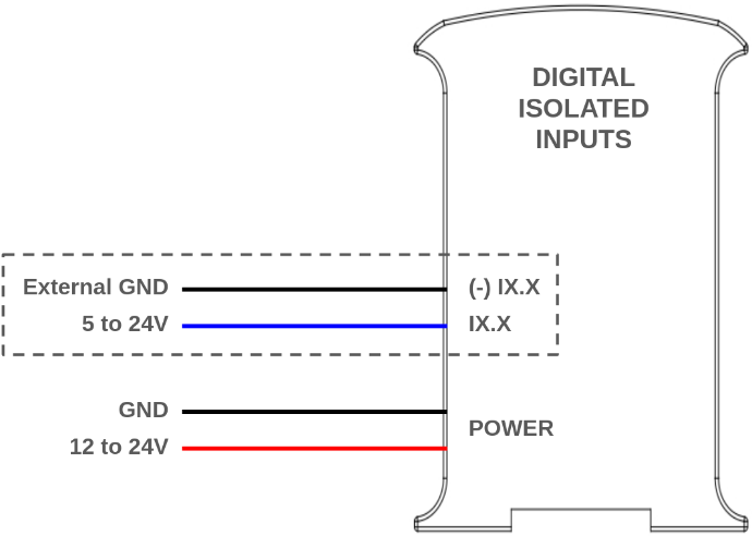
- Digital isolated inputs (5 - 24 Vdc): these inputs are opto-isolated, which means they have an extra protection and they use an external ground pin for reference. They are the pins from IX.0 to IX.6, where X is 0,1 or 2 depending on the zone.
- Digital non-isolated input (5 - 24 Vdc): these inputs are not opto-isolated, and they use the internal GND of the PLC as reference. They are the same as the analog inputs, going from IX.7 to IX.12, with X being 0, 1 or 2 depending on the zone.
You can identify them with the following symbols:

5V - 24V isolated input

5V - 24V non-isolated input
The next diagrams illustrate the necessary connections to properly use both inputs as digital:

Software setup
Here is a simple example of using an digital input using Python:
To test the code you can interconnect the chosen pin with the 5V and 3.3V pins of the Raspberry PLC. Remember to change the pin and the PLC model according to your requirements and make sure you have installed all the packages needed to program the PLC explained on this blog.
The following post might also be of interest: Basics about digital inputs of a Raspberry PLC.
Interrupt inputs
Some of the digital inputs in the Raspberry PLC are interrupt capable, which means they can be used with ISRs (interrupt service routine) to trigger certain code execution when an event (a change of state in the pin) is detected. There are two pins of this type each zone: IX.5 and IX.6. They are used and connected as regular digital isolated inputs, and the interrupts are programmed through software. These pins are directly connected to the Raspberry Pi, which means they can be used as GPIO:
Analog/Digital | Relay | GPIO |
0.5 | 0.0 | GPIO 13 |
0.6 | 0.1 | GPIO 12 |
1.5 | 1.0 | GPIO 27 |
1.6 | 1.1 | GPIO 5 |
2.5 | 2.0 | GPIO 26 |
2.6 | 2.1 | GPIO 4 |
Software setup
This is an example of how to use the interrupt pins. In this case we are using Python and the RPi.GPIO library. Look at how the "add_event_detect" function configures the interrupt setting the pin, the interrupt type (for example falling) and the callback of the function to execute when the interrupt is triggered.
To know more about the interrupt inputs, check the following post: How to program Raspberry industrial PLC interrupt inputs with Python.
Analog outputs
Analog outputs on the Raspberry PLC enable the generation of analog voltage levels to control external devices. These outputs translate digital values, represented by an N-bit number, into corresponding analog signals. The analog outputs utilize an external ground (GND) as a reference. The analog output specifications for these PLCs include:
- Voltage range: from 0 to 10 Vdc.
- Resolution: 12 bits, which means the read values can range between 0 and 4095.
The analog outputs are the ones between AX.0 and AX.7, with X being 0, 1 or 2 depending on the zone. You can identify the analog inputs on your device with the following symbol:

0 - 10V analog output
The next diagram illustrates the necessary connections to properly use an analog output:

Software setup
Here is a simple example of using an analog output using Python:
Remember to change the pin and the PLC model according to your requirements and make sure you have installed all the packages needed to program the PLC explained on this blog.
The following post might also be of interest: Basics about Raspberry Pi PLC analog outputs.
Digital outputs
The Raspberry PLC digital outputs can provide a low (0 Vdc) or high (up to 24 Vdc) value. These outputs are labeled as QX.X, and can be identified with the next symbol:

Digital output (PWM optional)
The output high value can range between 5 and 24 Vdc. This voltage needs to be set using two pins located next to the outputs: QVdc and COM(-). For instance, should you wanna set the output to 24V, the QVdc pin should be connected to 24V and the COM(-) pin to GND. The following diagram illustrates an example connection:

Software setup
Here is a simple example of using a digital output using Python:
Remember to change the pin and the PLC model according to your requirements and make sure you have installed all the packages needed to program the PLC explained on this blog.
The following post might also be of interest: Basics about digital outputs of Raspberry PLC.
PWM output
In the Raspberry Pi based PLCs, all the digital outputs can be used as PWM outputs.
The output high value can range between 5 and 24 Vdc. As when using them as simple digital outputs, this voltage needs to be set using two pins located next to the outputs: QVdc and COM(-). For instance, should you want to set the output to 24V, the QVdc pin should be connected to 24V and the COM(-) pin to GND. The following diagram illustrates an example connection.
The following diagram illustrates an example connection:

The following blog might be of interest: How to work with PWM outputs on industrial Raspberry PLC.
Relay output
A relay is an electromagnetic switch controlled by an electric signal. In Industrial Shields units these devices are already integrated in their boards. The relays included in the Raspberry PLC have the following specifications:
- Maximum DC current: 3A at 30Vdc.
- Maximum AC current: 5A at 250Vac
Each relay output has two terminals, and is labelled as RX.X. The following diagram illustrates the connections:

Software setup
Here is a simple example of using a relay output using Python:
Remember to change the pin and the PLC model according to your requirements and make sure you have installed all the packages needed to program the PLC explained on this blog.
Communications
Ethernet
Ethernet is the technology that is most commonly used in wired local area networks ( LANs ).
A LAN is a network of computers and other electronic devices that covers a small area such as a room, office, or building. It is used in contrast to a wide area network (WAN) , which spans much larger geographical areas. Ethernet is a network protocol that controls how data is transmitted over a LAN. Technically it is referred to as the IEEE 802.3 protocol. The protocol has evolved and improved over time to transfer data at the speed of a gigabit per second.
Our Raspberry Pi family incorporates both an integrated W5500 IC and the own Ethernet port of the Raspberry.
WX5500 is a Hardwired TCP/IP embedded Ethernet controller that provides easier Internet connection to embedded systems. This chip enables users to have Internet connectivity in their applications by using the single chip in which TCP/IP stack, 10/100 Ethernet MAC and PHY are embedded. The W5500 chip embeds the 32Kb internal memory buffer for the Ethernet packet processing. With this chip users can implement the Ethernet application by adding the simple socket program. SPI is provided for easy integration with the external microcontroller.
Hardware
Make sure that your PLC is powered (12-24Vdc). Just with USB is insufficient power to power up the Ethernet communication.
Switch configuration:
For the Ethernet communication
protocol there isn’t any switch that affects it, so it doesn't matter
the configuration of the switches to implement Ethernet communication.
Used pins:
For Ethernet communication with eth0 interface, there aren't any Raspberry Pi used pins.
However, for Ethernet communication with eth1
interface, the used Raspberry Pi pin is GPIO7, which is connected and
already internally assembled to the W5500 Ethernet controller. You can
easily access to the Ethernet port, as it is located at the top of the
communications layer.
Ethernet hardware configuration must be plug and play.
Software
Make sure that you have followed correctly the OS installation guide.
Software Configuration:
Once
the hardware configuration is done, it is possible to use the Ethernet
port as you would do with any other Linux computer. There isn't any need
to install extra libraries to begin with it.
RS-485
RS485 also known as TIA-485(-A), EIA-485, is a standard defining the electrical characteristics of drivers and receivers for use in serial communications systems. Electrical signaling is balanced, and multipoint systems are supported.
Our Raspberry Pi Based PLCs incorporate two integrated circuit MAX485.
MAX485 is a low-power and slew-rate-limited transceiver used for RS-485 communication. It works at a single +5V power supply and the rated current is 300 μA. Adopting half-duplex communication to implement the function of converting TTL level into RS-485 level, it can achieve a maximum transmission rate of 2.5Mbps. MAX485 transceiver draws supply current of between 120μA and 500μA under the unloaded or fully loaded conditions when the driver is disabled.
There is internally installed half duplex MAX485 receiver and MAX485 transmitter. If you are working on full duplex , you will use the MAX485 half duplex to receive data and MAX485 transmitter to send the data.
Hardware
Make sure that your PLC is powered (12-24Vdc). Just using the USB is insufficient to power up the Ethernet communication.
Switch configuration:
For the RS-485 communication protocol
there isn’t any switch that affects it, so it doesn't matter the
configuration of the switches to implement RS-485 communication.
Used pins:
For RS-485 communication protocol, the used pins
are the ones corresponding to SPI1, which are not accessible through
the PLC pins.
Software
Make sure that you have correctly followed the OS installation guide.
Software Configuration:
Once
the hardware configuration is done, it is possible to use the RS-485
with very little configuration. If you are interested in knowing how to
configure it, you can follow this guide.
Serial TTL
Serial TTL is a protocol for serial communication that is used in many embedded microcontrollers for asynchronous communication. A serial port sends the data in a bit by bit sequence, and because it is asynchronous communication, there isn't any clock signal that synchronizes the data. The UART ("Universal Asynchronous receiver-transmitter") circuitry handles the synchronization through start and stop bits, supposing that both devices are working at the same baud speed.
Being TTL means that the used logic levels are '0' (GND) or '1' (Vcc, in this case 3.3V). Unlike RS-485 or RS-232, it doesn't use voltage differences and it's full duplex by default (TX and RX in separated cables + GND).
The Raspberry PLC family has only one Serial port in pins RX/TX (GPIO15 and GPIO14 respectively). It can be accessed by configuring it with the stty command or through Serial libraries for programming languages like C++ (iostream, standard library) or Python (pyserial).
Hardware
Make sure that your PLC is powered (12-24Vdc).
Switch configuration:
For the Serial communication protocol
there isn’t any switch that affects it, so it doesn't matter the
configuration of the switches to implement Serial communication.
Used pins:
For Serial communication protocol, the used pins
are the ones corresponding to the Raspberry's serial ports (GPIO14/TX
and GPIO15/RX).
Software
Make sure that you have followed correctly the OS installation guide.
Software configuration:
For the serial communication there
isn’t any switch that affects it, so it doesn't matter the configuration
of the switches to implement Serial communication.
I2C
I2C is a synchronous protocol which uses 2 cables, one for the clock (SCL) and one for the data (SDA). This means that the master and the slave send data through the same cable, which is controlled by the master, who also creates the clock signal. I2C does not use slave selection, but addressing.
I2C is a serial communications protocol. The speed is 100 Kbit/s in standard mode, but it allows speeds of up to 3.4 Mbit/s. It is a very used bus in the industry, mainly to communicate microcontrollers and their peripherals in integrated systems. It is also used to communicate integrated circuits among themselves, normally residing in a same PCB (printed circuit board).
Hardware
Make sure that your PLC is powered (12-24Vdc).
Switch configuration:
To achieve I2C communication there
isn't any switch that affects it, it is always enabled. So it does not
matter the configuration of the switches to implement I2C communication.
Used pins:
For I2C communication protocol the defined pins
are the ones corresponding to the Raspberry Pi (GPIO2 for SDA and GPIO3
for SCL).
Software
Make sure that you have followed correctly the OS installation guide.
Software configuration:
First you will need some libraries to get I2C working in the Raspberry PLC:
sudo apt-get install -y python3-pip
pip3 install adafruit-blinka
Once these packages are installed, it is possible to start using I2C with Python. You can follow this guide to learn how you can program an I2C scanner, a program that searches for available devices in the bus.
SPI
SPI is a synchronous communication protocol bus that has a master-slave
architecture. Slave devices cannot initiate communication, nor exchange
data with each other directly. Only the master can select to which slave will communicate with through the SS (slave select) pin.
SPI1
is internally assembled with the RS-485 transmitter and receiver. And
SPI0, which is available through the Raspberry PLC pins, is shared with
Ethernet W5500 IC. The GPIO8 pin acts as the SS pin for an external
device. All these pins must work at 3.3V.
Hardware
Make sure that your PLC is powered (12-24Vdc).
Switch configuration:
To achieve SPI communication there
isn't any switch that affects it, it is always enabled. So it doesn't
matter the configuration of the switches to implement SPI communication.
Used pins:
For SPI communication protocol the defined Raspberry Pi pins are showed in the chart below:
SPI | Raspberry PLC | Raspberry Pi pinout |
MOSI | MOSI | GPIO10 |
MISO | MISO | GPIO9 |
SCLK | SCK | GPIO11 |
SS0 | GPIO8 | GPIO8 |
SS1 | Internally assembled | GPIO7 |
Software
Make sure that you have followed correctly the OS installation guide.
Software configuration:
First you will need some libraries to get SPI working in the Raspberry PLC:
sudo apt-get install -y python3-pip
pip3 install spidev adafruit-blinka
Once these packages are installed, it is possible to start using SPI with Python. You can follow this guide to learn how you can use a Raspberry PLC to communicate using this protocol.
Wi-Fi/Bluetooth
Wi-Fi is one of the most important technological developments of the modern age. Similar to other wireless connection types, like Bluetooth, it's a radio transmission technology built upon a set of standards to allow high-speed and secure communications between a wide variety of digital devices, access points and hardware. It makes it possible for Wi-Fi capable devices to access the internet without the need for wires. It can operate over short and long distances, be locked down and secured, or open and free. It's incredibly versatile and easy to use.
Bluetooth is a another wireless technology standard. Bluetooth was developed as a way to exchange data over a short range. Operates in the 2400-2483.5 MHz range within the ISM 2.4 GHz frequency band. Data is split into packets and exchange through one of 79 designed Bluetooth channels (each of which have 1 MHz in bandwidth).
All products of the Raspberry Pi family incorporate WiFi/Bluetooth connection.
To setup Wi-Fi in the Raspberry PLC, you can follow this guide.
And if you want to know how to use Bluetooth to, for example, communicate the Raspberry PLC with an Android Phone, you can follow this guide.
Extra features
UPS Shield
All Raspberry PLC Family devices include the UPS Shield. It is a Plug & Play UPS
Smart Shield that provides 5 seconds of electricity in front of a power
supply cut off. This extra time of electricity provides that the
Raspberry follow a correct Shut Down process, avoiding any SD corruption issue. The recharge time of the UPS is less than 1 minute, and the reconnecting time is less that 20 seconds.
If
you want to execute specific commands during an UPS shutdown, you can
edit the "/etc/rpishutdown/hooks/pre-poweroff" file and put them in
there. You may also need to give the file execution permissions with the
"sudo chmod ugo+x /etc/rpishutdown/hooks/pre-poweroff " command.
Check this post for more information.
RTC (UPS Shield)
The UPS Shield contains a RTC DS3231 integrated circuit communicating via I2C-bus with the Raspberry Pi.The term real-time clock is used to avoid confusion with ordinary hardware clocks which are only signals that govern digital electronics, and do not count time in human units. RTC should not be confused with real-time computing, which shares the acronym but does not directly relate to time of day.
Although keeping time can be done without an RTC, using one has its benefits:
- Low power consumption (important when running from alternate power).
- Frees the main system for time-critical tasks.
- Sometimes more accurate than other methods.
There is a 3.3V lithium coin cell battery supplying the RTC, we recommend using the CR2032 battery. The Raspberry Pi RTC Modules is based on the DS3231 chip. The DS3231 serial real-time clock is a low-power, full binary-coded decimal (BCD) clock/calendar. Address and data are transferred serially through I2C. The clock/calendar provides seconds, minutes, hours, day, date, month, and year information. The end of the month date is automatically adjusted for months with fewer than 31 days, including corrections for leap year. The clock operates in either the 24-hour or 12-hour format with AM/PM indicator. The DS3231 has a built-in power-sense circuit that detects power failures and automatically switches to the backup supply. Timekeeping operation continues while the part operates from the backup supply.
Check this post for more information.
3.3 Vdc Signals
These pins can be programmed according to Raspberry features such as I/Os operating at 3.3V, or any additional features present in the pins:
Serial – RX/TX:
The Serial protocol can work also as a 3.3V
pin. If using these pins, the Serial communication cannot be working at
the same time.
SPI0 – MISO/MOSI/SCK/GPIO8(SS):
These pins can only work as
a 3.3V pins if the W5500 Ethernet IC is not going to be used. As the
W5500 uses SPI to communicate with the Raspberry board, both behaviors
cannot happen at the same time.