Introduction
In this post, we are going to explain how to do the basics in order to work with digital outputs of Industrial Shields Raspberry Pi programmable logic controllers. Reading this post, you will understand how to connect and configure the digital outputs of your industrial Raspberry Pi PLC controller.
Previous readings
We recommend you read the following posts in order to understand the program of this blog. We used the following blog posts to do this example:
Requirements
In order to work with digital outputs, you will need any of our industrial controllers for industrial automation:
Configuring the switches
Most of the digital outputs are always connected to the internal Raspberry, but in a few cases, the user can choose between a special peripheral configuration or a GPIO by changing the position of the Dip Switches.
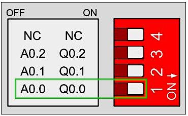
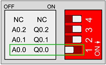
Each switch can select only one configuration. For example, in this case, you are watching the GPIOs configuration of an open source PLC Raspberry Pi 21+. If you put the switch to the right position (ON) in the lower one, the output Q0.0 will be activated and you will be able to work as digital. If the switch is in the left position (OFF), you will activate the output as analog. Keep in mind each switch has two different configurations: you must select the right (ON) or the left (OFF) option.

A0.0 Disabled - Q0.0 Enabled

A0.0 Enabled - Q0.0 Disabled
Hardware
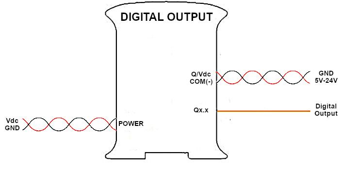
All the digital outputs are optoisolated (they use the same GNDs as the PLC). The image below shows how to connect a digital output to your PLC:

Software
How to work with Bash Scripts
Raspberry Pi PLC has default bash scripts for working with the inputs. All the inputs and outputs scripts must be executed from the correct path. It depends on the shield type of the I/O executed. In function of the shield of the I/O that you need to activate, you must execute the scripts from a specific path:
Analog/Digital Shields
> cd /home/pi/test/analog
Relay Shield
> cd /home/pi/test/relay
The set function will initialize the pin. You will provide the pin with which you are going to work and the value that will be set. For the digital option, a logical 1 will turn on the pin while a 0 will stop it.
By default, if no value option is provided, it will be initialized as a 1 for the Digital outputs. If any other options are chosen, an error code will warn you. In order to call the function, you will do the following:
> ./set-digital-output <output> <value>
There are some pins that both can work as digital or analog. In this case, if you have used these pins before in either digital or analogic and you want to switch their mode, you must call the set function, providing a stop to the value option; otherwise, there will be a system error. If a reboot is done, it is not necessary to do it.
The pins which can operate with both Analog/Digital configurations are:
| Q0.5 | Q1.5 | Q2.5 |
| Q0.6 | Q1.6 | Q2.6 |
| Q0.7 | Q1.7 | Q2.7 |
Example:
> ./set-digital-output Q0.5 1
> ./set-digital-output Q0.5 0
> ./set-digital-output Q0.5 stop
> ./set-analog-output A0.5 50
How to work with Python
The bash commands are the base for easily working with the Raspberry Pi based PLC. In order to work with python files, if you want to interact with the IOs of the PLC, you will have to call these scripts.
To edit the files, you will be working with the Nano editor included by default and Python3.
> nano digital_outputs.py
Python allows you to execute a shell command that is stored in a string using the os.system() function. In order to work with it, you will need to import its library at the beginning of the file. In addition, you will need to include the time library to summon a 2 seconds delay.
import os
import time
In this example program, you will be blinking some of the industrial Raspberry PLC digital leds. In order to do it, you will implement a loop that will constantly open up and shut them off in an interval of 2 seconds.
import os
import time
os.system("echo Start")
while True:
	try:
		os.system("sudo ./set-digital-output Q0.0 1")
		os.system("sudo ./set-digital-output Q0.1 1")
		os.system("sudo ./set-digital-output Q0.2 1")
		os.system("sudo ./set-digital-output Q0.3 1")
		os.system("sudo ./set-digital-output Q0.4 1")
		os.system("sudo ./set-digital-output Q0.5 1")
		time.sleep(2)
		os.system("sudo ./set-digital-output Q0.0 0")
		os.system("sudo ./set-digital-output Q0.1 0")
		os.system("sudo ./set-digital-output Q0.2 0")
		os.system("sudo ./set-digital-output Q0.3 0")
		os.system("sudo ./set-digital-output Q0.4 0")
		os.system("sudo ./set-digital-output Q0.5 0")
		time.sleep(2)
	except KeyboardInterrupt:
		os.system("sudo ./set-digital-output Q0.0 0")
		os.system("sudo ./set-digital-output Q0.1 0")
		os.system("sudo ./set-digital-output Q0.2 0")
		os.system("sudo ./set-digital-output Q0.3 0")
		os.system("sudo ./set-digital-output Q0.4 0")
		os.system("sudo ./set-digital-output Q0.5 0")
		os.system("echo End")
		break
In order to execute the Python program, you will call it the following:
> python3 digital_outputs.py
For exiting the program just press ^C.
Basics about digital outputs of Raspberry PLC