Modbus RTU and Modbus TCP with Python and Node-RED
Lesson 4: Modbus RTU and Modbus TCP
Modbus is the most widespread protocol to connect PLCs with sensors, drives, energy meters and SCADA systems. A Raspberry PLC can talk to all of them: Modbus RTU over its RS-485 ports and Modbus TCP over Ethernet. In this lesson you will understand how Modbus works and build a working master and slave in Python, plus the Node-RED equivalent.
By the end of this lesson you will be able to:
- Explain the difference between Modbus RTU and Modbus TCP and when to use each.
- Identify Modbus data types and the most common function codes.
- Implement a Modbus RTU and a Modbus TCP master and slave with
pymodbus. - Build a Modbus master in Node-RED.
1. Modbus
Modbus is a client/server (historically master/slave) data communication protocol used worldwide with PLCs. It runs over serial lines or over Ethernet and supports communication with many devices on the same cable or network. The Raspberry PLC supports Modbus RTU over RS-485 and Modbus TCP over Ethernet.
A Modbus command can instruct a device to:
- Change the value of one or more registers (write a coil or a holding register).
- Send back one or more of its values (read a coil or a holding register).
- Read a physical input (discrete input or input register).
1.1 Modbus RTU
Modbus RTU is the most common implementation. It is used over serial lines (RS-485, or RS-232) and uses a compact binary representation of the data. Each frame is delimited by idle periods, as shown in the figure.
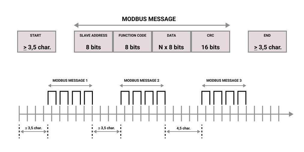
Every device on the bus has a unique address (1 to 247; address 0 is the broadcast address, which nobody answers). Only the master can start a communication; the slaves only reply to the requests addressed to them. The serial parameters (baud rate, parity, stop bits) must be identical in every device of the bus, so check the manual of each device.
1.2 Modbus TCP
Modbus TCP carries the same Modbus messages over TCP/IP, usually on port 502. It removes the address limit of the serial bus and integrates with standard Ethernet networks, switches and SCADA systems. The device is identified by its IP address, and the unit identifier is kept for gateways to RTU networks.
| Modbus RTU | Modbus TCP | |
|---|---|---|
| Physical layer | RS-485 / RS-232 | Ethernet |
| Addressing | Slave address 1-247 | IP address and port |
| Typical use | Field devices: meters, sensors, drives | PLCs, SCADA, gateways |
Security note: Modbus has no authentication or encryption. Keep it inside a segmented control network, protect it with a firewall, and never expose port 502 to the Internet.
2. Data types
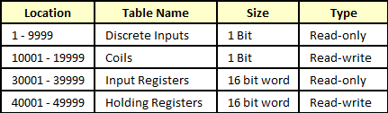
Modbus data is divided into coils and registers. Coils are digital: they can only be ON (1) or OFF (0); some represent inputs and others outputs. Registers are 16-bit unsigned values (0 to 65535, or 0 to FFFF in hexadecimal). A single register cannot hold negative numbers, decimals or values above 65535; for 32-bit values and floating-point numbers, devices use two consecutive registers, and the word order is defined by the manufacturer. The table summarises the four object types.
3. Function codes
Modbus is a request/response protocol, and the services are defined by function codes. The function code is encoded in one byte; when a client sends a request, it tells the server which action to perform. Code 0 is not valid and values from 128 to 255 are used for exception responses. Some function codes add sub-function codes to define several actions. The list of codes:
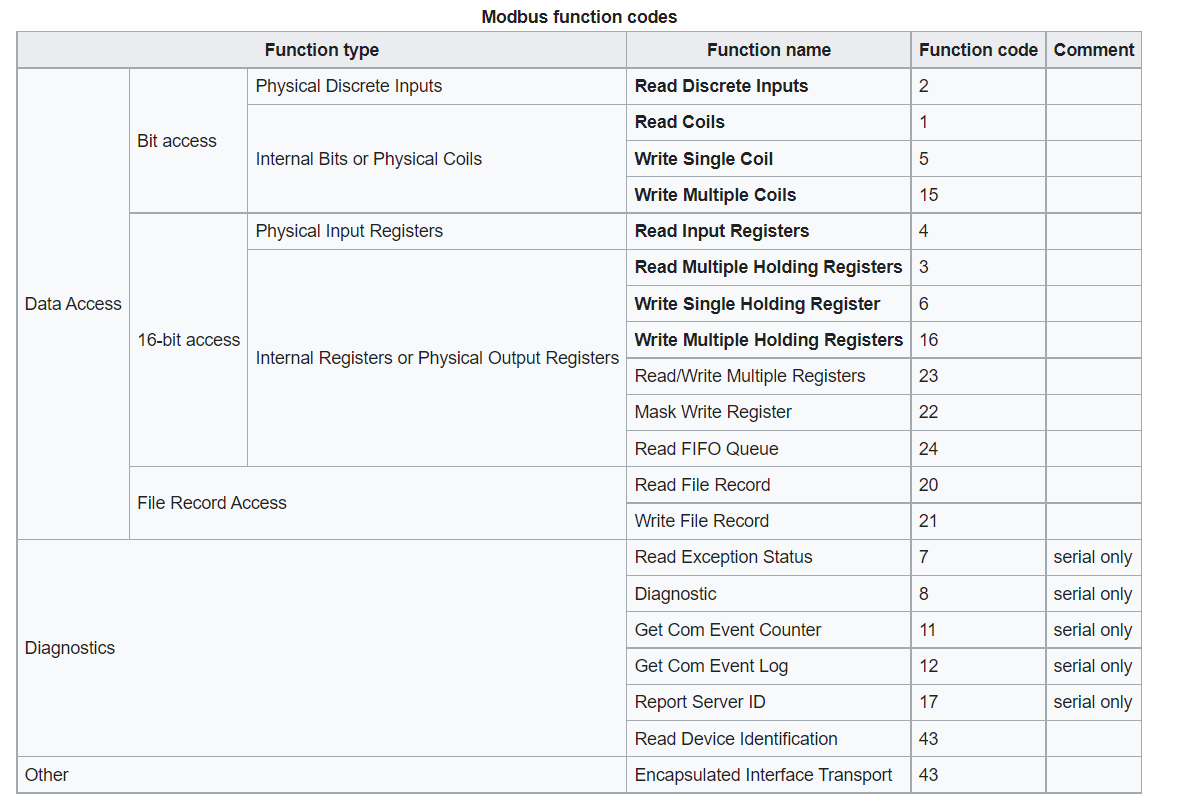
In practice you will use these most: FC 1 (read coils), FC 2 (read discrete inputs), FC 3 (read holding registers), FC 4 (read input registers), FC 5 (write single coil), FC 6 (write single register), FC 15 (write multiple coils) and FC 16 (write multiple registers).
4. Software
Industrial Shields does not provide its own Modbus library because there are complete libraries compatible with the Raspberry PLC. We recommend pymodbus, which implements both Modbus RTU and Modbus TCP in Python. The post on pymodbus with Raspberry PLC explains the basics in more depth.
The pymodbus API changes between major versions, so the examples in this lesson are written for version 3.6.9. Install it in a virtual environment:
python3 -m venv ~/modbus-env
. ~/modbus-env/bin/activate
pip install pymodbus==3.6.9 pyserial
5. Examples
5.1 Modbus RTU with Python
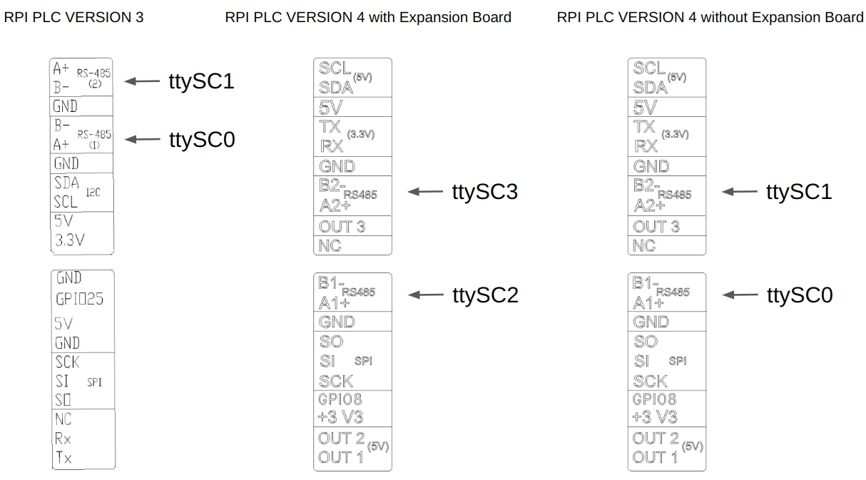
This example shows the master/slave communication with pymodbus. You need two Raspberry PLCs, one as the master and the other as the slave. Before running the code, power both PLCs and connect their RS-485 ports (A+ with A+, and B- with B-). The figure shows the ports for each Raspberry PLC version. The examples use the ttySC0 port.
Slave (program it in the first Raspberry PLC):
from pymodbus.server import StartSerialServer
from pymodbus.transaction import ModbusRtuFramer
from pymodbus.datastore import (
    ModbusServerContext,
    ModbusSequentialDataBlock,
    ModbusSlaveContext
)

# Data blocks for the four Modbus object types
store = ModbusSlaveContext(
    di=ModbusSequentialDataBlock(0, [0x0] * 1000),
    co=ModbusSequentialDataBlock(0, [0x0] * 1000),
    hr=ModbusSequentialDataBlock(0, [0x0] * 1000),
    ir=ModbusSequentialDataBlock(0, [0x0] * 1000))
context = ModbusServerContext(slaves=store, single=True)

# Start the Modbus RTU server on a serial port
# Here we use the /dev/ttySC0 port of the Raspberry PLC
StartSerialServer(context=context,
    port='/dev/ttySC0',
    framer=ModbusRtuFramer,
    baudrate=9600)
Master (program it in the second Raspberry PLC):
from pymodbus.client import ModbusSerialClient
from pymodbus.transaction import ModbusRtuFramer

# Create a Modbus RTU client
client = ModbusSerialClient(port='/dev/ttySC0',
    framer=ModbusRtuFramer,
    baudrate=9600,
    timeout=1)

if not client.connect():
    raise SystemExit("Could not open the serial port")

# Slave address (1 to 247; 0 is the broadcast address)
slave_address = 1

# Write 5 holding registers starting at address 0
register_address = 0
num_registers = 5
data_to_write = [10, 20, 30, 40, 50]
response = client.write_registers(register_address,
    data_to_write,
    slave=slave_address)

if not response.isError():
    print("Write successful")
else:
    print("Error writing registers:", response)

# Read the 5 holding registers back
response = client.read_holding_registers(register_address,
    num_registers,
    slave=slave_address)

if not response.isError():
    print("Read successful:", response.registers)
else:
    print("Error reading registers:", response)

# Close the connection
client.close()
If the communication works, the master prints:
Write successful
Read successful: [10, 20, 30, 40, 50]
If it fails: check A+/B- polarity, that both sides use the same baud rate, and that no other process uses the serial port. A timeout usually points to wiring or serial parameters.
5.2 Modbus RTU with Node-RED
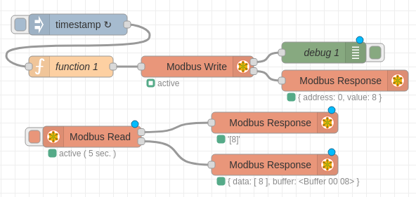
The next lesson introduces Node-RED, so it is better to try this example after Lesson 5 if you have never used it. The flow implements a Modbus RTU master:
- Install the
node-red-contrib-modbuspalette. The Modbus nodes appear in the left panel. - Place the nodes and connect them as in the figure.
- Configure the Inject node to send data every 5 seconds and write this code in the Function node:
if (context.hasOwnProperty('num')) {
    context.num = context.num + 1;
} else {
    context.num = 0;
}

msg.payload = context.num;

return msg;- In the Modbus Write node: configure the server with Type: Serial, Serial port:
/dev/ttySC0, Serial type: RTU and Baud rate: 9600. Set FC 6 (Preset Single Register) on address 0. - In the Modbus Read node: configure the same server, FC 3 (Read Holding Registers), address 0, quantity 1 and a poll rate of 5 seconds.
The flow writes and reads register 0 of the slave. As the slave you can use the Python code of the previous example (remember to set the unit ID to the slave address you use).
5.3 Modbus TCP with Python
This test uses the same logic as the RTU example, over Ethernet. You need two Raspberry PLCs and 3 Ethernet cables: each PLC connects to a PC (to load the code) and the two PLCs connect to each other. The two Ethernet ports behave differently, so connect both PLCs through the top Ethernet connector.
Slave: it creates a TCP server at the address and port you set. Use a port above 1024 (for example 5020) for tests, because port 502 requires administrator rights:
from pymodbus.server import StartTcpServer
from pymodbus.datastore import (
    ModbusServerContext,
    ModbusSequentialDataBlock,
    ModbusSlaveContext
)

store = ModbusSlaveContext(
    di=ModbusSequentialDataBlock(0, [0x0] * 1000),
    co=ModbusSequentialDataBlock(0, [0x0] * 1000),
    hr=ModbusSequentialDataBlock(0, [0x0] * 1000),
    ir=ModbusSequentialDataBlock(0, [0x0] * 1000))
context = ModbusServerContext(slaves=store, single=True)

# Change the address and port to match your network
StartTcpServer(context=context, address=("10.10.10.20", 5020))
Master: it writes and reads some registers on the slave. Set the host and port of your slave:
from pymodbus.client import ModbusTcpClient

# Change the host and port to match your slave
client = ModbusTcpClient(host='10.10.10.20', port=5020, timeout=3)

if not client.connect():
    raise SystemExit("Could not connect to the slave")

slave_address = 1
register_address = 0
num_registers = 5
data_to_write = [10, 20, 30, 40, 50]

response = client.write_registers(register_address, data_to_write, slave=slave_address)
if not response.isError():
    print("Write successful")
else:
    print("Error writing registers:", response)

response = client.read_holding_registers(register_address, num_registers, slave=slave_address)
if not response.isError():
    print("Read successful:", response.registers)
else:
    print("Error reading registers:", response)

client.close()
Remember that the two PLCs must have IP addresses in the same network (for example 10.10.10.20 and 10.10.10.21 with mask 255.255.255.0).
5.4 Modbus TCP with Node-RED
To use Modbus TCP in Node-RED, take the RTU flow and change the server of the Modbus Write and Modbus Read nodes to Type: TCP with the IP address and port of your slave. You can use the Python TCP slave above.
Next step
The next lesson builds on this to create visual flows and dashboards in Node-RED. To see which Raspberry PLC fits your Modbus network, visit the Raspberry PLC range at www.industrialshields.com.
There are no comments for now.
to be the first to leave a comment.