Basic communications: I2C, SPI, RS-485, serial TTL, Ethernet, MQTT and RTC
Lesson 1: Basic communications on a Raspberry PLC
A Raspberry PLC rarely works alone. In a plant it sits between sensors, drives, other controllers and the IT network, so the first skill to build is choosing the right interface for each link and testing it before it goes on a machine. This lesson walks through the interfaces of the Raspberry PLC, with a bench test for each one.
By the end of this lesson you will be able to:
- Choose between I2C, SPI, RS-485, serial TTL and Ethernet for a given link.
- Verify both RS-485 ports and connect a Raspberry PLC to an M-Duino over RS-485.
- Exchange data over Ethernet with HTTP and MQTT, with authentication enabled on the broker.
- Read and set the hardware clock (RTC) so your logs keep correct timestamps without a network.
| Interface | Typical industrial use | Distance / topology |
|---|---|---|
| I2C | On-board peripherals (RTC) and nearby sensors | Centimetres, shared bus |
| SPI | Fast peripherals such as ADCs, displays or memories | Centimetres, one master |
| RS-485 | Field bus: Modbus RTU, sensors, drives, other PLCs | Up to 1,200 m, multi-drop, differential |
| Serial TTL | Board-to-board links and command-based modules | Short, point to point, not for noisy environments |
| Ethernet | Modbus TCP, MQTT, HTTP, SSH, SCADA | Star network, switch based |
1. I2C
I2C (Inter-Integrated Circuit) is a serial bus that uses two lines: SCL for the clock and SDA for the data. Many devices share the same two lines, each with its own address. On the Raspberry PLC it is also the bus used by the on-board RTC (see section 8), so enable it with sudo raspi-config (Interface Options) before you start.
To test it, connect an Adafruit MMA8451 accelerometer to the I2C pins and read values from it. You need 4 wires: 2 for power and 2 for I2C.
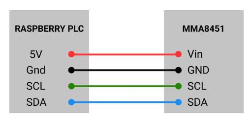
First check that the sensor answers on the bus. It should appear at address 0x1d (or 0x1c depending on the SA0 pin):
sudo apt install i2c-tools
i2cdetect -y 1
Then install the Adafruit library in a virtual environment (recent Raspberry Pi OS versions do not allow system-wide pip installs) and run the example:
python3 -m venv --system-site-packages ~/venv
. ~/venv/bin/activate
pip install adafruit-circuitpython-mma8451
git clone https://github.com/adafruit/Adafruit_CircuitPython_MMA8451.git
cd Adafruit_CircuitPython_MMA8451/examples
python3 mma8451_simpletest.py
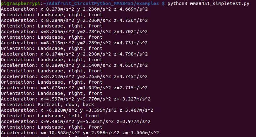
You should see the acceleration values and the orientation change as you move the sensor:
2. SPI
SPI (Serial Peripheral Interface) is a synchronous bus with one master and one or more slaves. It uses four signals: SCK (clock), MOSI (master out, slave in), MISO (master in, slave out) and SS (slave select). It is faster than I2C, which is why it is used for converters, displays and memories.
3. SPI connection schemes
3.1. Independent slaves
Each slave has its own SS line, while SCK, MOSI and MISO are shared.
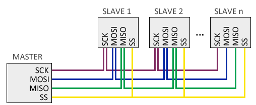
This scheme suits a low number of slaves, because every slave adds a line: total lines = 3 + number of slaves.
3.2. Cascade (daisy chain) connection
With many slaves, the number of lines can become impractical. In a daisy chain the slaves share SCK and SS, and each slave passes the data to the next one until it returns to the master.
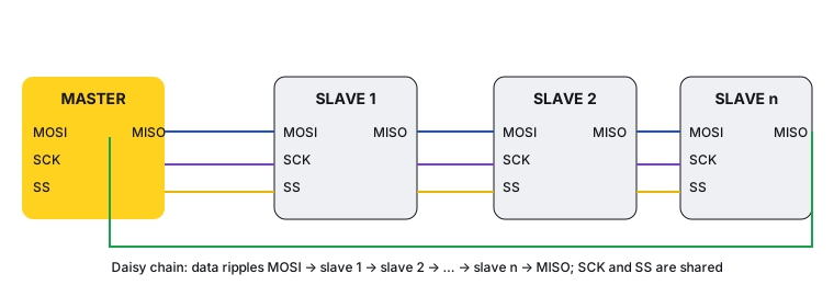
The data has to travel through all the slaves before the transfer is complete, so the effective bus speed is lower than with independent slaves.
4. RS-485
RS-485 is the workhorse of the factory floor: differential signalling, multi-drop topology and long distances, which is why Modbus RTU runs on it (see the course First Steps with Modbus). The Raspberry PLC gets its two RS-485 ports from the SC16IS752 chip, a low-power UART with a 5 V supply, average current of 300 uA and a maximum speed of 2.5 Mbps. Each port is half-duplex; to obtain a full-duplex link, use one port to send and the other to receive.
Note: the Raspberry PLC uses the serial ports ttySC0 and ttySC1. On the Raspberry PI PLC v4 the ports are ttySC2 and ttySC3.
Field wiring good practice: use shielded twisted pair, keep the A/B polarity consistent along the whole bus, add a 120 Ω termination resistor at each end of the line only, and connect the shield at one end.
4.1. Verification test
This test checks both RS-485 ports against each other. Connect A1+ with A2+ and B1- with B2-. Then create a script:
nano testRS485.sh
chmod u+x testRS485.sh
and paste these lines:
#!/bin/bash

stty -F /dev/ttySC0 115200 raw -echo
stty -F /dev/ttySC1 115200 raw -echo

# Listen on ttySC1 for 3 seconds in the background
timeout 3 cat /dev/ttySC1 > /tmp/rs485.txt &
sleep 0.5

# Send "OK" from ttySC0
echo "OK" > /dev/ttySC0
wait

RESULT=$(cat /tmp/rs485.txt)
if [ "${RESULT}" = "OK" ]; then
  echo "RS-485 test passed: OK"
else
  echo "RS-485 test failed: received '${RESULT}'"
fi
Everything received on /dev/ttySC1 is stored in /tmp/rs485.txt. The script sends "OK" from /dev/ttySC0 and, if the wiring is right, /dev/ttySC1 receives it. timeout stops the listener by itself, so no process is left running in the background.
4.2. Connection to an M-Duino
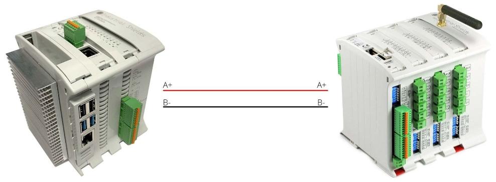
Once both ports work, connect the Raspberry PLC to an M-Duino PLC (here, an M-Duino 54 ARA+). You will make each PLC send data to the other and check that it arrives. Wire A+ of the M-Duino to A+ of the Raspberry PLC and B- to B-.
The Arduino sketch starts with this setup:
// Include Industrial Shields libraries
#include "RS485.h"

//// IMPORTANT: check switches configuration

void setup() {
    // Begin serial port
    Serial.begin(9600);
    // Begin RS485 port
    RS485.begin(115200);
}
Test 1: M-Duino to Raspberry PLC. The M-Duino waits for data on its serial port and forwards it over RS-485. Meanwhile the Raspberry PLC listens for 5 seconds and prints what it receives. In the M-Duino:
void loop() {
  // wait bytes in the serial port
  if (Serial.available()) {
    byte tx = Serial.read();
    // and send it to the RS-485 port
    RS485.write(tx);
  }
}
In the Raspberry PLC, create a new bash script:
#!/bin/bash

stty -F /dev/ttySC0 115200 raw -echo

# Listen for 5 seconds and print what arrives
timeout 5 cat /dev/ttySC0
Type some text in the Arduino IDE serial monitor and it will show up in the Raspberry PLC terminal.
Test 2: Raspberry PLC to M-Duino. The Raspberry PLC sends "Hello World!" from ttySC0 and the M-Duino prints it in the serial monitor. Add these lines before setup() in the M-Duino sketch:
int Period = 1000; // Data sending period in ms
unsigned long Time;
String rcv_message;
and use this loop():
void loop() {
  // Print received data when available
  if (RS485.available()) {
    rcv_message = RS485.readString();
    Serial.println(rcv_message);
  }
}
On the Raspberry PLC, run this script:
#!/bin/bash
stty -F /dev/ttySC0 115200 raw -echo
echo "Hello World!" > /dev/ttySC0
5. Serial TTL
Serial TTL (Transistor-Transistor Logic levels) is the UART signalling found in most microcontrollers. It is cheap and simple, full-duplex and point to point, which makes it ideal to talk to a command-based module on the same panel. Because it is not differential like RS-232 or RS-485, avoid it over long distances or in electrically noisy environments, where signals degrade quickly. For anything that leaves the cabinet, use RS-485.
Remember to cross the lines: RX of the Raspberry PLC goes to TX of the other device, and TX to RX.
5.1. Software test
5.1.1. Unix approach
Following the "everything is a file" philosophy, you can configure /dev/ttyS0 (the serial port of the Raspberry PLC) with stty and then read and write it like any file:
stty -F /dev/ttyS0 raw speed 115200 -echoThis sets raw mode (received bytes are not interpreted), a speed of 115200 baud and disables echo. After that, cat and echo read and write the port, and so can any program, for instance:
with open("/dev/ttyS0", "rb") as f:
    while True:
        byte_s = f.read(1)  # read 1 byte
        if byte_s:
            print(byte_s)
        else:
            break
The program prints all the characters available in the buffer until it is empty.
5.1.2. Library approach
The Unix approach needs no dependencies, but a more complex system is easier to build with a library. In Python, pyserial handles serial port access across operating systems:
import serial

port = "/dev/ttyS0"
baudrate = 115200
serial_port = serial.Serial(port=port, baudrate=baudrate, bytesize=8, stopbits=1, timeout=1)

while True:
    try:
        n = serial_port.read(1)
        print(n)
    except KeyboardInterrupt:
        break

serial_port.close()
6. Ethernet
The Raspberry PLC has 2 Ethernet ports: the one of the Raspberry Pi itself and a second one based on the W5500 chip. Both are accessible to the CPU and can be used for any Ethernet protocol (SSH, TCP, UDP, Modbus TCP, MQTT...). Their default IP addresses are 10.10.10.20 for eth0 and 10.10.11.20 for eth1.
Having two ports lets you separate networks, for example the machine or control network on one port and the plant or IT network on the other. Keeping control traffic away from the IT network is a basic good practice in industrial cybersecurity.
6.1. HTTP
HTTP is the protocol behind the web, and it is also the easiest way to integrate a PLC with APIs, dashboards and MES/ERP systems.
6.1.1. Python requests
A GET request with Python (always set a timeout so a network problem cannot block your program):
import requests

url = 'https://www.industrialshields.com'
x = requests.get(url, timeout=5)

print(x.text)
Save it in a file (do not call it http.py, it would conflict with a Python module) and run it with python3 myfile.py. A POST request:
import requests

url = 'https://www.industrialshields.com/'
obj = {'key': 'value'}
x = requests.post(url, json=obj, timeout=5)

print(x.text)
The variable x has several useful attributes:
links: returns the header links.ok:Trueifstatus_codeis less than 400, otherwiseFalse.reason: text corresponding to the status code.status_code: number that indicates the status (200 is OK, 404 is Not Found...).text: content of the response in Unicode.url: URL of the response.
6.1.2. Bash requests
In bash, use curl:
curl -X GET https://www.industrialshields.com/
curl -X POST -d "key1=value1&key2=value2" https://www.industrialshields.com/
7. MQTT
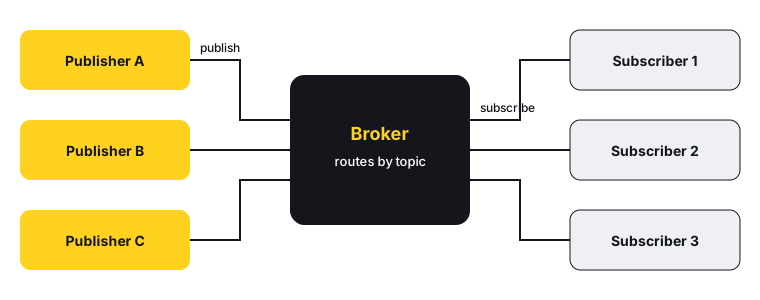
MQTT (Message Queuing Telemetry Transport) is the standard OASIS messaging protocol for IoT and IIoT applications, on top of TCP/IP. It follows a publish/subscribe model: a publisher sends data on a topic, and every subscriber to that topic receives it. Publishers and subscribers never talk to each other; a broker receives the messages and distributes them to the right destinations. That decoupling is what makes MQTT a good fit for connecting many machines to one data platform.
7.1. Eclipse Mosquitto
Eclipse Mosquitto is an open source broker that implements MQTT 5.0, 3.1.1 and 3.1, and it also provides a C library to write clients. Install the broker and the command-line clients on the Raspberry PLC:
sudo apt install mosquitto mosquitto-clientsSince version 2.0, Mosquitto only accepts connections from the PLC itself by default. To accept clients over Ethernet, create a configuration file and require a user and password; an open broker on a plant network lets anyone read and publish to your machines.
First create the password file (it asks for the password):
sudo mosquitto_passwd -c /etc/mosquitto/passwd plcuserThen create /etc/mosquitto/conf.d/network.conf with:
listener 1883 0.0.0.0
allow_anonymous false
password_file /etc/mosquitto/passwd
and restart the service:
sudo systemctl restart mosquitto.serviceNow connect a PC to the Raspberry PLC through Ethernet (give the PC an address in the same network, for example 10.10.10.22) and subscribe to a topic:
mosquitto_sub -h 10.10.10.20 -u plcuser -P 'your-password' -t "topic"From a second terminal, publish a message:
mosquitto_pub -h 10.10.10.20 -u plcuser -P 'your-password' -t "topic" -m "hello this is a test"The subscriber shows the message:

If you get Connection refused, check that the file with the listener line is in /etc/mosquitto/conf.d/, that the service restarted without errors (systemctl status mosquitto) and that the IP addresses are in the same network. For traffic that leaves the machine network, add TLS (port 8883) as well.
8. RTC
The RTC (Real Time Clock) keeps the time of day. In a PLC this matters because logs, alarms and production records need a trustworthy timestamp even when there is no network and no NTP server. A hardware RTC is useful because:
- It is more accurate than other clock systems.
- It is independent from the CPU of the main system.
- It has a low power consumption, which is important in embedded systems.
The Raspberry PLC includes a DS3231 chip, which communicates over I2C (so I2C must be enabled) and is backed by a button battery (CR1216 or CR1220). To work with the hardware clock, try these commands in a terminal:
- Read the hardware clock:
sudo hwclock -r - Set a custom date and update the timestamps in
/etc/adjtime:sudo hwclock --set --date="2000-04-22 16:25" - Copy the system time to the RTC:
sudo hwclock -w - Set the system time from the RTC:
sudo hwclock -s - More information:
man hwclock
Next step
You now have the building blocks to connect a Raspberry PLC to the field (RS-485), to other controllers and to the plant network (Ethernet, MQTT). Continue with the next lesson of the course, or explore the Raspberry PLC range at www.industrialshields.com.
There are no comments for now.
to be the first to leave a comment.