Expansion boards: 4G/LTE connectivity and CAN bus
Lesson 3: Expansion boards on a Raspberry PLC
Expansion boards add communication interfaces to a Raspberry PLC without changing the controller. Up to 2 expansion boards can be used at the same time. This lesson covers the two that solve the most common connectivity needs in the field: 4G/LTE, to reach a machine that has no wired network, and CAN bus, to talk to drives, sensors and vehicles that use CAN.
By the end of this lesson you will be able to:
- Install a 4G/GPRS expansion board and bring up the
ppp0connection. - Troubleshoot the serial ports and the
pppdservice. - Configure the CAN bus board, bring up
can0and test it withcandumpandcansend.
1. Expansion boards
Expansion boards (also called expansion modules) are hardware components added to a PLC to extend its capabilities. Slot 1 is the default one and slot 2 is the second one.
2. 4G/GPRS
The GPRS Click board is based on the u-blox SARA-R412M module. A cellular link is the usual solution to monitor remote or mobile machines (pumping stations, generators, agricultural equipment) where there is no wired network.
- Model: SARA-R412M.
- Technologies: LTE Cat M1 (4G), NB-IoT and GPRS / eGPRS.
- Key features: quad-band GSM, IPv4 / IPv6, dual-stack.
- Applications: remote monitoring, asset tracking, surveillance and security, point-of-sale terminals.
Security note: a cellular connection places the PLC on a public network. Prefer a private APN or a VPN, do not expose services such as SSH or MQTT to the Internet, and use authentication on every service.
2.1 Installation
Plug the GPRS Click into one of the expansion slots and follow these steps.
1. Download, make executable and run the setup script for your Raspberry PLC version.
Raspberry PLC V4:
wget https://apps.industrialshields.com/main/rpi/rpiplc_v4/setup-gprs.sh
chmod +x setup-gprs.sh
sudo ./setup-gprs.sh
Raspberry PLC V6:
wget https://apps.industrialshields.com/main/rpi/rpiplc_v6/setup-sara.sh
chmod +x setup-sara.sh
sudo ./setup-sara.sh
2. Enter the data requested by the script:
- APN credentials: APN, ISP username and ISP password (your mobile operator provides them).
- RAT (Radio Access Technology), one of: LTE Cat M1 (4G), NB-IoT (narrow band) or GPRS / eGPRS.
3. Service created by the script. The script creates a service called pppd (/lib/systemd/system/pppd.service) that runs a Python file, network-setup.py, every time the Raspberry PLC boots, so the connection comes back by itself after a power cut. Follow the log with tail -f /var/log/syslog or journalctl -f. After 50 to 120 seconds, an interface called ppp0 should appear.
4. Verify that the interface exists:
ip a show ppp05. Test the connection by pinging through ppp0:
ping 8.8.8.8 -c4 -I ppp0
ping www.google.com -c4 -I ppp0
2.2 Troubleshooting
1. Check that the serial ports are available. The ports /dev/ttySC0 and /dev/ttySC1 must be visible:
ls /dev/ttySC*/dev/ttySC0 corresponds to expansion slot 1 (default) and /dev/ttySC1 to expansion slot 2.
If the ports are not listed, install a new image or run the install.sh script. The steps depend on your version:
- Raspberry PLC V4: install this image or run this install.sh script.
- Raspberry PLC V6: install this image or run this install.sh script.
Reboot the PLC afterwards and check again.
2. Check whether the serial port is in use. If you cannot communicate with the module, see which process occupies the port:
sudo lsof /dev/ttySC0If it is busy, stop the process with sudo kill [PID], where PID is the process ID shown by lsof. Also make sure the serial port is configured for hardware use, not as a login console: sudo raspi-config → Interface Options → Serial Port → login shell: No → serial port hardware: Yes.
3. Verify that the pppd service is running:
systemctl status pppd.service4. Test manually if ppp0 is missing. First stop the pppd service (and check-ppp0 if it exists):
sudo systemctl stop check-ppp0.service   # if it exists
sudo systemctl stop pppd.service
Then run the Python script created by the installation, where RAT is gprs, nb-iot or lte-m:
python3 /usr/local/bin/network-setup.py [RAT]3. CAN bus
CAN (Controller Area Network) is a robust, differential, multi-master bus designed for noisy environments. It is used in mobile machinery, drives, battery systems and many industrial sensors, and it is the physical layer of higher-level protocols such as CANopen. The CAN expansion board uses the MCP2515 controller:
- Model: MCP2515, CAN 2.0B.
- Speed: up to 1 Mb/s.
- Features: receive buffer, masks and filters, filtering on the first two data bytes, three transmit buffers with prioritisation and abort.
- Interface: high-speed SPI (10 MHz).
- Applications: communication with any CAN device and with the protocols built on CAN.
3.1 Configuration
1. Enable SPI:
sudo raspi-config # Interface Options > SPI > Yes2. Edit the boot configuration file according to your operating system version: sudo nano /boot/config.txt for Bullseye, or sudo nano /boot/firmware/config.txt for Bookworm. Make sure these lines are present.
For expansion slot 1:
dtoverlay=spi1-3cs
dtoverlay=mcp2515,spi1-2,oscillator=10000000,interrupt=4,speed=125000
For expansion slot 2:
dtoverlay=mcp2515,spi0-1,oscillator=10000000,interrupt=4,speed=125000If the lines are missing, add them at the end of the file, save it and reboot the PLC.
3. Verify that the MCP2515 initialised:
dmesg | grep mcpYou should see something like mcp251x spi1.2 can0: MCP2515 successfully initialized.
4. Configure the CAN network interface. Make sure a file named can0 exists in /etc/network/interfaces.d/ with this content (if it is missing, create it and reboot):
auto can0
iface can0 inet manual
	pre-up /sbin/ip link set can0 type can bitrate 500000 triple-sampling on restart-ms 100
	up /sbin/ifconfig can0 up
	down /sbin/ifconfig can0 down
The bitrate (500000 bit/s here) must be the same on every node of the bus. Change it to match your network.
5. Check that the can0 interface appears:
ip a show can03.2 Test
Connect two CAN nodes as shown in the picture (CANH to CANH, CANL to CANL) and follow the steps for a simple test. On a real bus, use twisted-pair cable and a 120 Ω termination resistor at each end of the line.
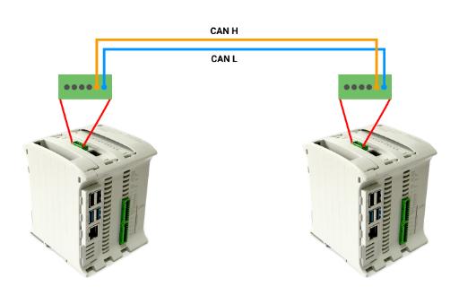
1. Install the CAN utilities:
sudo apt install can-utils2. Receive. In a terminal of the first PLC, leave can0 listening:
candump can03. Send. On the second PLC, send a test frame with ID 111 and data FF:
cansend can0 111#FFIf the configuration is correct, the first Raspberry PLC shows the frame with ID 111 and data FF.
Which board for which job?
| Need | Board |
|---|---|
| Reach a remote or mobile machine without wired network | 4G/GPRS (LTE Cat M1, NB-IoT, GPRS) |
| Talk to CAN devices (drives, sensors, CANopen networks) | CAN bus (MCP2515) |
Next step
The next lesson uses these communications to exchange data with Modbus and build a SCADA with Node-RED. Discover the Raspberry PLC range at www.industrialshields.com.
There are no comments for now.
to be the first to leave a comment.