Lesson 3. Control PLC outputs from Node-RED
#3 How to interact with Outputs
In the chapter #3 is shown how to interact with our outputs of an Industrial Shields PLC. Before starting this chapter make sure that you have achieved the steps of the previous chapters. During the course we will be increasing the Node-RED application, so in this one we already have the inputs in the dashboard.
Requirements
- Node-RED and NodeJS installed and running
- Node-RED Dashboard 1.x (node-red-dashboard) installed
- Mosquitto MQTT broker installed and running
- PLC with the chapter #1 code running
Once the requirements are achieved we will start explaining how the output architecture will work.
Outputs Architecture
As commented before, this course is designed to be used with a M-Duino PLC family. As an example, we use a M-Duino 21+.
In our M-Duino 21+ we have 8 digital outputs (from Q0_0 to Q0_7), apart from that we know that three of these digital outputs can work as analog outputs. So, in our example there will be 5 digital outputs (from Q0_0 to Q0_4) and 3 analog outputs (from A0_5 to A0_7). To extend the Node-RED App to more outputs, the procedure is exactly the same.
Adding a new tab
To have a better organization of our dashboard, it would be perfect to place a new tab where we can control our outputs and not to mix them with our inputs. Obviously, this is an example in your own application. You can place the different components regarding your needs.
So, in the first part of this chapter, we will see how to add a new tab.
Go to the Node-RED user interface through your browser. At the top right side select the menu and click on flow -- > Add a new flow. Then, go to a renamed and called Output flow.
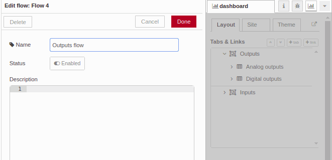
After that, an automatic tab will be created. On our Layout, we will be able to named and add the new groups. Name your new tab Outputs and add two new groups, one called Analog Outputs and the other called Digital Outputs.
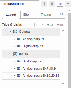
Now, we are ready to add the dashboard items:
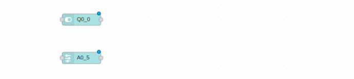
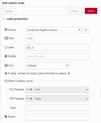
1. Add a Switch and a Slider.
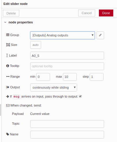
2.Click on them and name them.
3.Select also the group to be placed.
4.Select Analog outputs for the slider and Digital Outputs for the switch.
Do not forget to add the topic at the bottom of the Edit switch node. A for Analog Outputs and Q for Digital outputs.
Sending the MQTT Message
Since then we have placed the items to our dashboard. So, now it's time to proceed to connect these items to the MQTT broker, in other words send a message with the topic A and Q.
First, it's required to relate the switch and slider to the right JS object. Select the Change function and configure it as follows:
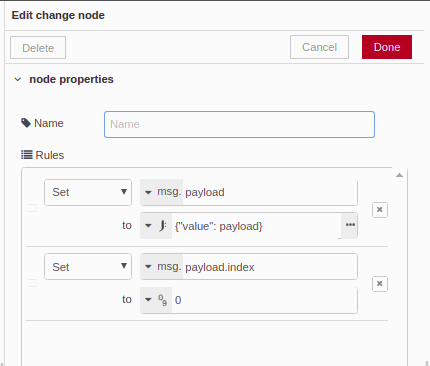
*For every different input we must set the index value. In this case it is a "0" because we are configuring the Q0_0.
The change function will add a new content. Now, we have an index apart of the payload where we have the value of the switch or the analog slider. Besides the index, we need to add the zone. So, add another change function and add the zone parameter. Take look on the next picture:
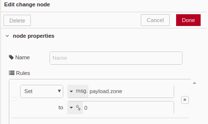
*For every different zone we must set the proper value of the zone. In this case it is a "0" because we are configuring the zone 0 (between Q0_0 and A0_7).
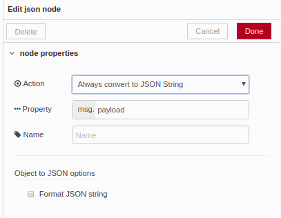
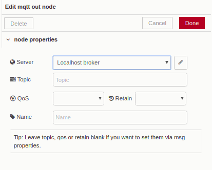
Now, we have the JS object set properly and we just need to create the JSON and send it to the MQTT broker. Take the JSON function and edit it as "Always convert to JSON String". Then, add the MQTT output function and select the broker. In our case our broker is running on our computer so we select "Localhost broker".
*Remember that we have added the topic into the switch function. We can also define it into the MQTT output function, but then we will have to create two different nodes.
Take a look at the example of how to set the JSON function and the MQTT output function.
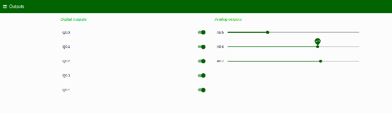
Finally add the entire I/Os that you want to use and place the switch and the sliders where you want using the
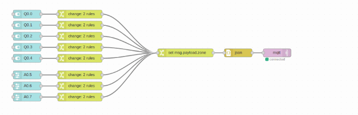
Our Node-RED program should look like the picture below:
Commenting is not enabled on this course.