Case study · Winery · M-Duino PLCs
Four PLCs, one network. From the label to the cellar.
A labelling line and a wine cellar on one network of four Arduino PLCs.
A winery has two rooms. In one, each bottle gets its label. In the other, it waits to be sold.
Four PLCs share one network so that the line, the belts and the cellar work as one system.
This case describes a project for a winery. The customer is not named. The original material gives the architecture: a master PLC and three slave PLCs on LoRa, a router, a server and a Panel PC on Ethernet, a labelling machine on RS-485, a laser engraver on a wireless link, photoelectric sensors in the racks, a temperature and humidity sensor, an LCD on I2C, and relays for the belts, the air conditioning and the dehumidifier. It names three of the PLCs: M-Duino 57R+, M-Duino 21+ WiFi / Bluetooth and M-Duino 19R+. It does not publish the program, the set points, the message format or the model of the master PLC. The five belts are the example layout of the original text. The panels, numbers and messages on this page are examples of a typical way to do it.
The challenge
Two rooms, five belts, two machines and a cellar. One system.
The winery needed to control and monitor two rooms. In the first room, a line labels and engraves the bottles. The second room is the cellar, where the bottles are stored for later sale. Conveyor belts take the bottles from one room to the other and send them to a rack with free space. All the data goes to a server, and a Panel PC is the point of monitoring and control.
Label and engrave each bottle
A labelling machine and a laser engraver work on the same line. A PLC gives each machine its job.
Send bottles where there is space
Belts take the bottles to the cellar. When a rack is full, the bottles must go to the next one.
Keep the cellar right for wine
The customer asked to control the temperature and the humidity of the cellar, so that the wine stays in good condition.
See it all from one point
All the process data goes to a server, and a Panel PC shows it in real time.
Many devices, many interfaces
Belt motors, a machine with a serial port, an engraver, sensors, a small display and a server do not talk the same way. The design gives each device the link that suits it, and joins the PLCs with radio instead of cables between the rooms.
How it works
Three loops: the network, the line, the cellar.
Each panel shows one part of the system. Press the buttons. The panels are illustrative simulations: rack sizes, times, set points and messages are examples, not data from the installation.
One master on the radio. One door to the server.
The master PLC controls the three slave PLCs over LoRa, a long range radio. It sends the process data through a router to the server over Ethernet, and the server passes it in real time to the Panel PC. The slaves do not need a cable to the server: the master speaks for them. Cut the radio link to one PLC, or the Ethernet, and see what a typical design does. Read what LoRa is.
- LoRa between the master and PLC 2, 3 and 4
- Ethernet from the master to the router and the server
- The server feeds the Panel PC in real time
Master PLC (example)
Illustrative simulation. Example values, shown faster than real time. The case says that the master controls the slaves over LoRa and sends the data to the server. It does not publish the message format or the timing. A typical way to do it: the master asks each slave in turn and waits a short time for the answer, so only one radio talks at a time.
Each bottle gets its label. Each rack gets its turn.
PLC 3 runs the labelling station: it talks to the labelling machine over RS-485 and to the laser engraver over Bluetooth, with no cable. PLC 2 switches the motors of the belts with its relays. Belt 1 is in the labelling line, belt 2 takes the bottles to the cellar, and three more belts feed the racks. Photoelectric sensors in the racks go to PLC 4. When a rack is full, PLC 2 stops its belt and starts the next one. Run the line and empty a rack.
- RS-485 to the labelling machine, Bluetooth to the engraver
- Relay outputs for the 220 V single-phase belt motors
- Rack full: its belt stops, the next one starts
PLC 2, 3 and 4 (example)
Illustrative simulation. Example values, shown faster than real time. Example rack size of 6 bottles. The case says that a photoelectric sensor tells when a rack is full, and that the belt of that rack then stops and the next one starts. Stopping the line when all racks are full is an example, not a published fact.
The cellar has its own climate. And its own screen.
PLC 4 reads a temperature and humidity sensor in the cellar. Depending on the selected values, it switches the air conditioning and the dehumidifier with its relays. The values are on the Panel PC and also on a small LCD in the cellar, on the I2C bus of the PLC. Change the weather and watch the relays. To run a full day of climate control in a closed room, open the Greenhouse climate simulator and choose the mushroom room.
- Temperature and humidity sensor on an input of PLC 4
- Relays for the air conditioning and the dehumidifier
- Values on the Panel PC and on an I2C LCD in the cellar
PLC 4 (example)
Illustrative simulation. Example values, shown faster than real time. Example set points: air conditioning on above 16 °C and off below 14.5 °C, dehumidifier on above 75 % and off below 68 %. The real set points of the installation are not published.
System architecture
How do four PLCs link a labelling line and a wine cellar?
This diagram follows the assembly scheme of the original case. The master PLC is the only one on Ethernet: router, server, then Panel PC. LoRa links it to PLC 2, 3 and 4. Each slave uses the interface that suits its devices: relays for the belts, RS-485 and a wireless link for the machines, inputs, relays and I2C in the cellar. The text says Bluetooth for the engraver; the scheme draws a Wi-Fi symbol (see the FAQ).
| Signal | Between | Type | Purpose |
|---|---|---|---|
| Process data | BetweenMaster PLC → router → server | TypeEthernet | PurposeAll the data of the system in one place |
| Live view | BetweenServer → Panel PC | TypeEthernet | PurposePoint of monitoring and control |
| Orders and states | BetweenMaster PLC ↔ PLC 2, 3 and 4 | TypeLoRa radio | PurposeThe master controls the three slaves |
| Belt motors | BetweenPLC 2 → 5 belts | TypeRelay outputs | PurposeStart and stop each belt (220 V single-phase motors) |
| Label jobs | BetweenPLC 3 ↔ labelling machine | TypeRS-485 | PurposeOne label for each bottle |
| Engraving jobs | BetweenPLC 3 ↔ laser engraver | TypeBluetooth (Wi-Fi symbol in the scheme) | PurposeEngraving with no cable |
| Rack full | BetweenPhotoelectric sensors → PLC 4 | TypeDigital inputs | PurposeCapacity of the racks |
| Next belt | BetweenPLC 4 → PLC 2 | TypeOver the PLC network | PurposeStop the belt of a full rack and start the next one |
| Temperature and humidity | BetweenSensor → PLC 4 | TypeInput (digital in the scheme) | PurposeClimate of the cellar |
| Cellar climate | BetweenPLC 4 → air conditioning and dehumidifier | TypeRelay outputs | PurposeSwitched by the selected values |
| Local display | BetweenPLC 4 → LCD in the cellar | TypeI2C | PurposeTemperature and humidity on site |
Why it works
The right link for each device. One network for the rooms.
Radio between the rooms
LoRa joins the PLCs without cables between the rooms. It carries short messages (up to 255 bytes), which is enough for orders and states. The original text gives a range of more than 15 km; walls, racks and tanks shorten it, so test the link on site.
One master speaks for the line
Only the master needs Ethernet. It collects the states of the slaves and sends them to the server, so the Panel PC sees the whole system from one source.
Each machine on its own interface
The labelling machine uses RS-485, the usual serial bus for this kind of machine. The engraver uses a wireless link, and the cellar display uses I2C. See RS-485 with Arduino and ESP32 based PLCs.
Relays where loads switch
The M-Duino 57R has 23 relay outputs for the belts. The M-Duino 19R has 8, for the air conditioning and the dehumidifier.
Two places to read the cellar
The Panel PC shows all the data. The I2C LCD in the cellar shows temperature and humidity to whoever is in the room. See how to work with an LCD on I2C.
Open source the team can change
The PLCs are programmed in the Arduino IDE, with Industrial Shields libraries and example codes for each interface. The same system can grow with more belts, racks or rooms.
Hardware used
Three M‑Duino PLCs named in the case.

M-DUINO ETHERNET PLC ARDUINO 57R
PLC 2, for the belts. An Arduino Mega 2560 based PLC for DIN rail with 49 I/O, 23 of them relays. The case chose it because its relay outputs can switch the 220 V single-phase motors of the belts.
- Role
- Conveyor belts: start, stop and switch to the next rack
- Inputs
- 18: 12 analog/digital (0-10 V, 10-bit), 6 digital optoisolated (5 to 24 Vdc), 6 with interrupt
- Outputs
- 31: 23 relays (4 A at 230 Vac, 2 A at 24 Vdc, resistive), 8 analog/digital/PWM (0-10 V)
- Comms
- Ethernet (W5500, 10/100), RS-485, RS-232, TTL serial, I2C, SPI
- Built in
- Real-time clock, microSD slot, USB
- Power and mounting
- 12 to 24 Vdc, DIN rail TS35, IP20, 0 to 60 °C
The case does not publish the power of the belt motors. A relay rating is for a resistive load, and a motor is not one. A typical way to do it: the relay switches the coil of a contactor or a motor starter with overload protection, with an RC snubber sized for the coil. On the LoRa network of this case, PLC 2 uses the LoRa version (see the M-Duino LoRa family datasheet).

M-DUINO ETHERNET PLC ARDUINO 21
PLC 3, for the labelling station. A compact Arduino Mega 2560 based PLC with 21 I/O and RS-485. In this case it talks to the labelling machine over RS-485 and to the laser engraver over Bluetooth.
- Role
- Jobs for the labelling machine and the laser engraver
- Inputs
- 13: 6 analog/digital (0-10 V, 10-bit), 7 digital optoisolated (5 to 24 Vdc), 2 with interrupt
- Outputs
- 8: 5 digital optoisolated (5 to 24 Vdc), 3 analog/digital/PWM (0-10 V)
- Comms
- Ethernet (W5500, 10/100), RS-485, RS-232, TTL serial, I2C, SPI
- Built in
- Real-time clock, microSD slot, USB
- Power and mounting
- 12 to 24 Vdc, DIN rail TS35, IP20, 0 to 60 °C
The case names the M-Duino 21+ WiFi / Bluetooth. The image and the link show the M-Duino 21 with Ethernet. The Wi-Fi and Bluetooth versions are in the M-Duino Wi-Fi & BLE family datasheet. PLC 3 needs LoRa to reach the master and Bluetooth to reach the engraver. The case does not say how the two radios are combined: ask us for the right version.
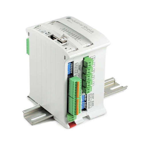
M-DUINO ETHERNET PLC ARDUINO 19R
PLC 4, in the cellar. An Arduino Mega 2560 based PLC with 17 I/O, 8 of them relays. In this case it reads the rack sensors and the climate sensor, switches the air conditioning and the dehumidifier, and drives the LCD on I2C.
- Role
- Rack sensors, cellar climate, local LCD
- Inputs
- 6: 4 analog/digital (0-10 V, 10-bit), 2 digital optoisolated (5 to 24 Vdc), 2 with interrupt
- Outputs
- 11: 8 relays (4 A at 230 Vac, 2 A at 24 Vdc, resistive), 3 analog/digital/PWM (0-10 V)
- Comms
- Ethernet (W5500, 10/100), RS-485, RS-232, TTL serial, I2C, SPI
- Built in
- Real-time clock, microSD slot, USB
- Power and mounting
- 12 to 24 Vdc, DIN rail TS35, IP20, 0 to 60 °C
The case does not publish the number of racks or sensors. Count one input for each rack sensor plus the climate sensor before you choose the model. For the compressor of an air conditioner, use the relay to give a command to its controller or to a contactor. On the LoRa network of this case, PLC 4 uses the LoRa version (see the M-Duino LoRa family datasheet).
Questions about this case
How do four PLCs share data in a winery?
In this case one master PLC talks to three slave PLCs over LoRa radio. The master is the only one on Ethernet: it sends the process data through a router to a server, and the server passes it in real time to a Panel PC. The slaves handle their own devices: the belts, the labelling station and the cellar.
Why LoRa between the PLCs, and how far does it reach?
LoRa avoids cables between the rooms and gives a long range with low power. It sends short messages, up to 255 bytes, which suits orders and states but not large files. The original text gives more than 15 km. That is an open field figure: inside a winery, walls, racks and tanks reduce it, so test the link where the PLCs will be. See What is LoRa? and the datasheet of the M-Duino LoRa family.
How does the line know which rack to fill?
Photoelectric sensors in the racks go to inputs of PLC 4. When the sensor of a rack says it is full, PLC 4 tells PLC 2, which stops the belt of that rack and starts the belt of the next one. The case says that the system can have any number of belts, depending on the size of the cellar.
Bluetooth or Wi-Fi to the laser engraver?
The text of the case says Bluetooth, to avoid wiring; the assembly scheme draws a Wi-Fi symbol on the same link. The M-Duino Wi-Fi & BLE versions have both. Choose the one that your engraver accepts, and check its command set. The labelling machine stays on RS-485, the usual bus for this kind of machine. See how to use an M-Duino Wi-Fi/BLE PLC over Bluetooth.
Can the relay outputs drive the belt motors?
The case chose relay PLCs to switch the 220 V single-phase motors of the belts. The relays of the M-Duino 57R are rated 4 A at 230 Vac with a resistive load, and a motor has a high starting current. The case does not publish the motor power. A typical way to do it: the relay switches a contactor or a motor starter with overload protection, as the motor maker and your local rules require.
Which parts of this case are facts, and which are examples?
Facts: a winery with two rooms, a labelling and engraving line and a cellar; four Arduino based PLCs, one master and three slaves on LoRa; a router, a server and a Panel PC on Ethernet; PLC 2 with relays for the belts; PLC 3 with the labelling machine on RS-485 and the engraver on a wireless link; PLC 4 with rack sensors, a temperature and humidity sensor, relays for the air conditioning and the dehumidifier and an LCD on I2C. Models named: M-Duino 57R+, M-Duino 21+ WiFi / Bluetooth and M-Duino 19R+. Examples: the five belts (an example in the original text), rack sizes, set points, times, messages and the polling method.
Download the case study
4-page PDF with the challenge, the logic, the architecture and the hardware. No form required.
Linking machines and rooms?
Tell us about your line and your cellar. An engineer will answer.
Tell us which machines you have and how they talk (RS-485, Ethernet, wireless), how far apart the rooms are, how many belts and racks you need, and what you want to see on the panel. We will propose the PLCs and the network.
- You get an answer from our technical team
- PLCs, radios and panel for your plant
- Arduino, ESP32 or Raspberry Pi based PLCs