Introduction
A Liquid-Crystal Display (LCD) is a flat-panel display or another electronically modulating optical device that uses the light-modulating properties of liquid crystals combined with polarizers. It is very common to use them to get and upgrade electronic systems and display the results. In this post, we are going to talk about how to use them using the I2C communications of your PLC controller.
Hardware requirements
Any of our industrial Programmable Logic Controllers
A liquid crystal LCD (In this example we will be using a 16x2)
I2C interface module and I2C wire
Wires
How to connect it?
There are a lot of liquid-crystal displays in the market; in our case, we will be using a 16x2 size DEM 16215 an HW-061 I2C interface module. For the industrial Arduino PLC we will use an M-Duino 50RRA+ WiFi/BT.
We will provide a 24V power to the PLC Arduino that will provide 5V to power the LCD. The LCD has 16 pins but we will only use a total of 12 as we will be working with a 4 bit data length interface. The pins that we will use for the characters are the ones 11 to 14.
Look for the I2C communication pins on the side of the controller Arduino since you will connect the SCL and SDA pins of the PLC to those of the I2C module. Then using the I2C wire you will connect the LCD display. Depending on your components, check out the documentation to know the pins to connect between the LCD and the I2C module.
Software interface
Our industrial controllers are programmed using Arduino Ide, which is a C language-based software. They can also be programmed using C directly but it is much easier working with Arduino IDE as it provides lots of libraries that help in the programming.
Industrial Shields provides boards to program the PLCs for industrial automation. Basically, you do not need to define the pins and whether they are inputs or outputs since everything is automatically configured using the boards.
To install Industrial Shields boards, this link explains everything:

Code
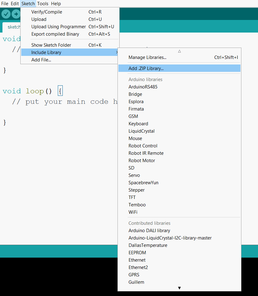
To work properly, the Wire and LiquidCrystal_I2C libraries must be included.
#include <Wire.h>
#include <LiquidCrystal_I2C.h>
First, you have to call the following statement to create the LiquidCrystal class and set up all the configurations. You will set the address of the I2C device and the number of rows and columns of your LCD. If the I2C address is unknown, you can check our post about how to know it.
LiquidCrystal_I2C lcd(0x3F, 16, 2);
When the display is turned on, it has default configurations, however, resetting the Arduino does not reset the LCD, so you cannot assume that it is in that state when a sketch is started (and the LiquidCrystal constructor is called). To set all the internal settings, you should call the begin function before doing anything.
lcd.begin();
The I2C Liquid Crystal library provides a wide range of options to work with it. However, you will only use some of them since they are the most important functions to quickly start working. For more precise use, see all the documentation on the library GitHub.
The ones that you will be using are the following:
lcd.print(“ x ”): This will work as the print function, printing the text on the LCD screen.
lcd.clear(): It will clear the display and set the cursor to position zero.
lcd.setCursor(uint8_t col, uint8_t row): This will set the cursor to the position you have selected.
lcd.backlight(): It will turn on the LCD backlight.
A code will be shown below to see how to display some text on the LCD:
#include <Wire.h>
#include <LiquidCrystal_I2C.h>
// Set the LCD address to 0x27 for a 16 chars and 2 line display
LiquidCrystal_I2C lcd(0x3F, 16, 2);
void setup()
{
	// initialize the LCD
	lcd.begin();
	// Turn on the blacklight and print a message.
	lcd.backlight();
	lcd.print("Industrial");
  lcd.setCursor(0,1);
  lcd.print("Shields!");
}
void loop(){}
How to work with an LCD using I2C in industrial automation