Case study · Sector: AGVs and mobile robots
The safety controller stops the AGV. The PLC runs the rest.
Lights, load sensors, charging and battery data on an ESP32 PLC that only reads the safety controller.
An AGV must stop for people. Nothing else on board may get in the way of that.
So the stop chain stays certified and separate, and an open PLC runs everything that is not safety.
Based on real installations of Industrial Shields customers in the AGV and mobile robot sector; data and names are not published. The split between the safety controller and the PLC, the signal list and the interfaces are a typical way to build it, drawn from what these makers buy and ask us. Vehicles, messages and panel values on this page are examples. The ESP32 PLC 21 FLEX is our option for this role, chosen by datasheet; it does not replace the safety controller.
The challenge
One vehicle, two kinds of signals.
An AGV or an AMR carries two kinds of logic. Safety functions protect people: emergency stop, detection of people with safety laser scanners, speed control and braking. ISO 3691-4 gives each one a required performance level, met with ISO 13849-1, and they run in a certified safety controller or safety relay. Around them sit many signals that are not safety functions: tower light and sound, load sensors on the top module, charging contacts, battery data, and the link to the navigation computer and the fleet manager. The maker needs a small controller for those, built in series, that never weakens the stop chain.
Keep the stop chain certified
Emergency stops, scanners and bumpers wired to the safety controller, which removes torque from the drives (STO) and applies the brakes.
Read, never override
The PLC reads the state of the safety controller to show it, log it and report it. It has no wire into the stop chain.
Run the auxiliaries
Tower light, sound, blue spot, load sensors, lift end positions and charging contacts on the I/O of the PLC.
Talk to the rest
Battery data over CAN, the navigation computer over Modbus TCP, events to the fleet manager over MQTT.
Safety is a separate job
The PLC in this design is a standard controller, not a safety controller. If the risk assessment calls a function a safety function, it goes to the certified safety controller, even if the PLC has a free input.
How it works
Three jobs: report the safety state, move the load, keep the battery in charge.
Each panel shows one job of the PLC on the vehicle. Press the buttons. The panels are illustrative simulations with example values, not data from a customer.
The safety controller decides. The PLC tells everyone.
The safety laser scanners have a warning field and a protective field. When a person enters the warning field, the navigation slows the vehicle down; this is not a safety function, and the PLC turns the light amber. When the protective field is broken or an emergency stop is pressed, the safety controller removes torque and brakes, on its own. The PLC only sees the result: it turns the light red, sounds the alarm and reports why the vehicle stopped. Walk in front of the vehicle.
- Warning field: navigation slows down, amber light
- Protective field: safety stop by the safety controller
- Emergency stop: reset at the vehicle, never from the PLC
Vehicle log (example)
- AGV 3 on its way to station 4.
Illustrative simulation. Example values, no data from a customer. The PLC has no output into the stop chain: in every button, the stop comes from the safety controller and the PLC only reads it. Speeds and fields depend on the vehicle and its risk assessment.
Dock, check, transfer, leave.
At a station, an AGV with a roller top module docks. The PLC checks the position and the handshake with the station, runs the rollers and watches the load sensors until the load is on board. Only then does it tell the navigation computer that the vehicle may leave. If a sensor does not change in time, the rollers stop and the fault is reported. Run a transfer, then block the load.
- Handshake with the station over I/O or Wi-Fi
- Load sensors at both ends of the rollers
- A timeout on every step
Transfer log (example)
- AGV 3 arriving at station 4.
Illustrative simulation. Example values, no data from a customer. Crushing and shearing points of the load handling are part of the risk assessment too; where they need a safety function, it runs in the safety controller, not in this program.
The PLC knows the battery before the fleet asks.
The battery management system (BMS) sends state of charge, current, temperature and alarms over CAN. The PLC reads them, passes them to the navigation computer and the fleet manager, and runs the charging side: contacts closed, charger enabled, end of charge. When the charge falls under the level set by the fleet, the vehicle goes to charge between missions. Drain the battery, then charge it.
- State of charge, current and temperature over CAN
- Charging contacts and charger enable on I/O
- Battery alarms to the fleet manager
Battery log (example)
- AGV 3, BMS data every second.
Illustrative simulation. Example values, no data from a customer. Charge levels, currents and the CAN messages come from the BMS manual of each battery. What the vehicle does on a battery alarm is a decision of the maker and its risk assessment.
System architecture
How do you split safety and auxiliary I/O on an AGV?
Safety devices (emergency stops, safety laser scanners, bumpers, speed monitoring) go to a certified safety controller, which removes torque from the traction drives and applies the brakes. The ESP32 PLC reads its status outputs and runs the auxiliary I/O: tower light, sound, load sensors, lift end positions and charging. Battery data arrives over CAN, the navigation computer talks Modbus TCP on Ethernet, and the fleet manager gets events over MQTT on Wi-Fi.
| Signal | Between | Type | Purpose |
|---|---|---|---|
| Protective field, emergency stop, bumper | BetweenDevices → safety controller | TypeSafety inputs, dual channel | PurposeSafety stop: STO and brakes, never through the PLC |
| Safety OK or safety stop | BetweenSafety controller → PLC | TypeDigital input, status only | PurposeLight, sound, log, report to the fleet |
| Emergency stop pressed | BetweenSafety controller → PLC | TypeDigital input, status only | PurposeTell the operator and the fleet why it stopped |
| Warning field occupied | BetweenScanner → navigation and PLC | TypeNon-safety output | PurposeSlow down (navigation), amber light (PLC) |
| Load present, end positions | BetweenSensors → PLC | TypeDigital input, 24 V | PurposeSteps and timeouts of the transfer |
| Rollers or lift | BetweenPLC → top module drive | TypeDigital output | PurposeRun the transfer |
| Tower light, sound, blue spot | BetweenPLC → signals | TypeDigital output | PurposeShow the state of the vehicle |
| Charging contacts, charger enable | BetweenContacts ↔ PLC | TypeDigital input and output | PurposeCharge between missions |
| Charge, current, temperature, alarms | BetweenBMS → PLC | TypeCAN, board option | PurposeSend to charge, report battery alarms |
| Mission, status, events | BetweenPLC ↔ navigation PC and fleet manager | TypeModbus TCP, MQTT | PurposeOne view of every vehicle |
Why it works
A certified stop chain, and an open controller beside it.
The certification stays put
The safety controller and its wiring keep their performance level. Changing the auxiliary program does not touch the safety validation.
Stops people can read
Because the PLC reads why the vehicle stopped, the light, the log and the fleet manager can say "emergency stop" or "protective field" instead of just "stopped".
Small enough for a vehicle
13 inputs and 8 outputs in a DIN rail housing, with Ethernet, RS-485, Wi-Fi and a CAN board option.
Built in series
One program for the whole fleet, in C++ with the Arduino IDE, updated without changing the hardware.
Open protocols
Modbus TCP to the navigation computer and MQTT to the fleet manager: open protocols that any team can read and test.
Room for the next module
If a top module needs more signals, a bigger ESP32 PLC of the same family keeps the same program base.
Hardware
One compact PLC for everything that is not safety.
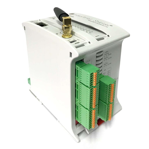
Our option for this roleESP32 PLC 21 FLEX
An industrial controller built on the dual-core ESP32, for DIN rail, programmed with the Arduino IDE. It has the inputs and outputs for the auxiliary functions of a vehicle, Ethernet for the navigation computer, Wi-Fi for the fleet, and the FLEX version takes one communication board: here, CAN for the battery management system.
- Role in this design
- Auxiliary I/O, state of the safety controller, BMS over CAN, link to navigation and fleet
- Processor
- ESP32 dual core, up to 240 MHz
- Inputs
- 13: 6 analog/digital (0-10 V, 11-bit), 7 digital optoisolated (5 to 24 Vdc), 2 of them with interrupt
- Outputs
- 8: 3 analog/digital/PWM (0-10 V, 12-bit), 5 digital optoisolated (5 to 24 Vdc)
- Wireless and option board
- Wi-Fi and Bluetooth LE built in; one option board: CAN here, or LoRa or 4G
- Wired
- Ethernet, RS-485, RS-232
- Programming
- Arduino IDE (C++)
- Power supply
- 12 to 24 Vdc
- Mounting
- DIN rail TS35, IP20, inside a cabinet
It is a standard controller, not a safety controller: do not wire it into the stop chain. A 24 V vehicle battery goes above 28 V while charging, and 48 V systems are common, so feed the PLC from a DC/DC converter. Check the shock and vibration of your vehicle against the datasheet and mount the PLC in the vehicle cabinet. For more signals, the ESP32 PLC 58 belongs to the same family.
Questions about this case
Can a PLC do the safety functions of an AGV?
A standard PLC cannot. ISO 3691-4 lists the safety functions of driverless industrial trucks, such as emergency stop, detection of people, speed control and braking, and gives each one a required performance level to be met with ISO 13849-1, often PL d. That needs a certified safety controller, safety relay or safety PLC, with safety devices such as safety laser scanners. A standard PLC like the ESP32 PLC can read the state of those devices and do everything that is not a safety function.
What does the PLC do on an AGV, then?
The auxiliary functions: tower light, sound and blue spot, load sensors and end positions of the top module, the rollers or the lift, charging contacts and charger enable, battery data, and the link to the navigation computer and the fleet manager. It also reads the state of the safety controller, so the vehicle can show and report why it stopped.
Can the PLC slow the vehicle down when a person is near?
The navigation can slow down with the warning field of the scanner, which is not a safety function, and the PLC can show it. The safety function is the protective field: the scanner and the safety controller stop the vehicle whatever the PLC does. Switching protective fields with speed is a safety function too, and belongs to the safety controller.
How does the PLC read the battery?
With the CAN board of the ESP32 PLC 21 FLEX. Many battery management systems speak CANopen or their own CAN protocol; the PLC program decodes the messages listed in the BMS manual. Check the bit rate and the protocol before you choose, and test with the real battery on the bench.
How does it talk to the navigation computer and the fleet manager?
A typical way: a Modbus TCP register map on Ethernet with the navigation computer (mission, status, charge, faults) and MQTT on Wi-Fi to the fleet manager for events. Wi-Fi drops in some corners of a plant, so the PLC keeps the events and sends them when the link returns. See MQTT logging that survives a lost link on an ESP32 PLC, and a Modbus RTU master on RS-485 if a drive or a top module speaks Modbus.
Does the same split apply to AMRs?
Yes. Mobile robots that move loads in industry are driverless industrial trucks under ISO 3691-4 in Europe; in North America, ANSI/RIA R15.08 covers industrial mobile robots. Safety functions in a certified safety controller, auxiliaries in a standard PLC that reads its state: the split is the same.
Download the case study
4-page PDF with the challenge, the logic, the architecture and the hardware. No form required.
Similar project?
Tell us about your vehicle. An engineer will answer.
Tell us which auxiliary signals your AGV or AMR has, which battery and BMS, how the navigation computer and the fleet manager talk, and how many vehicles a year you build. We will tell you which controller fits and how to keep it out of the stop chain.
- You get an answer from our technical team
- I/O count, CAN, Modbus TCP and MQTT
- Arduino, ESP32 or Raspberry Pi based PLCs