
To use Modbus RTU on an Arduino or ESP32 based PLC, connect the RS-485 port of the PLC to the bus (A+ to A+, B- to B-), open it with RS485.begin(baudrate, HALFDUPLEX, SERIAL_8E1) and create a ModbusRTUMaster or ModbusRTUSlave object from the Industrial Shields Modbus library. The master sends a request with a function such as readHoldingRegisters(slave, address, quantity) and reads the answer later with available(), because the library does not block.
This guide works for the M-Duino family, the Ardbox family with hardware RS-485, the ESP32 PLC family and the ESP32 PLC 14. It covers the wiring, the board selection in the Arduino IDE, a tested master sketch, a slave sketch, the function reference of the library and the errors you will see first. If you need the protocol itself (frame, function codes, CRC), read the Modbus RTU frame and function codes guide first.
How does a Modbus RTU transaction work on a PLC?
Modbus RTU is a master and slave protocol on a serial line, usually RS-485. Only the master starts a transaction. Each slave has an address from 1 to 247 and answers only the requests with its address.
- Step 1RequestThe master sends the slave address, a function code, the first register, the quantity and a CRC.
- Step 2SilenceA pause of at least 3.5 characters marks the end of the frame (1.75 ms above 19200 baud).
- Step 3AnswerThe slave checks the CRC and answers with the data, or with an exception code.
- Step 4Next slaveThe master reads the answer, or gives up after its timeout, and asks the next slave.
The Industrial Shields library follows these steps for you. Your sketch only sends the request and checks for the answer in loop().
Hardware and software you need
- One Arduino PLC (M-Duino or Ardbox) or ESP32 PLC as Modbus master.
- A second PLC, or any device with Modbus RTU on RS-485 (energy meter, frequency drive, temperature transmitter), as slave.
- A 12 to 24 Vdc power supply.
- A USB cable to program the PLC (type B on Arduino PLCs, micro USB on ESP32 PLCs).
- A twisted pair cable for RS-485 (two twisted pairs for full duplex).
- The Arduino IDE, the Industrial Shields boards and the Modbus library (also in Industrial Shields libraries).
Wire the RS-485 port of each PLC family
Power the PLC with 12 to 24 Vdc, connect the bus and set the communication switches. The full switch tables for each model are in the RS-485 tutorial for Arduino and ESP32 PLCs.
| PLC family | RS-485 terminals | Half duplex (2 wires) | Full duplex (4 wires) |
|---|---|---|---|
| M-Duino | A+, B-, Y+, Z- | A+ to A+, B- to B-. Bottom switch 1 OFF | A+ to Y+, B- to Z-, Y+ to A+, Z- to B-. Bottom switch 1 ON |
| Ardbox HF+ with hardware RS-485 | A+, B-, Y+, Z- | A+ to A+, B- to B- | Same as M-Duino. HD/FD with right top switch 1 (Analog) or 2 (Relay) |
| ESP32 PLC | A+, B- | A+ to A+, B- to B-. Switch 3 OFF | Not available |
| ESP32 PLC 14 | A+, B- | A+ to A+, B- to B-. No switch | Not available |
A Modbus RTU bus is almost always half duplex: one twisted pair, all devices in a line, and a 120 Ω termination resistor at each end. Connect the signal ground (GND) of the devices too when they have no common reference. The RS-485 basics explain why.
Select the board and the model in the Arduino IDE
| PLC | Tools > Board | Tools > Model |
|---|---|---|
| M-Duino | Industrial Shields AVR Boards > M-Duino [Extension] family | M-Duino [Module] |
| Ardbox | Industrial Shields AVR Boards > Ardbox [Extension] family | Ardbox [Module] HF+ w/HW RS-485 |
| ESP32 PLC | Industrial Shields ESP32 Boards > ESP32 PLC Family | ESP32 PLC [Module] |
| ESP32 PLC 14 | Industrial Shields ESP32 Boards > 14 IOS PLC Family | No model menu |
The ready-made sketches are in File > Examples > Modbus (or File > Examples > Tools40 > Modbus in older installations). There is one master example for each function code and one slave example.
Modbus RTU master example: read holding registers
This sketch reads 4 holding registers (40001 to 40004) from slave 1 every second and prints them on the serial monitor. It compiles without warnings for an M-Duino 21+ with the Industrial Shields AVR boards 1.2.1 and Modbus library 1.1.0. On an Ardbox HF+ with hardware RS-485 and on an ESP32 PLC the sketch does not change: their RS485 library has the same begin(baudrate, duplex, config).
// Modbus RTU master: read 4 holding registers from slave 1 every second
// M-Duino, Ardbox HF+ w/HW RS-485 and ESP32 PLC (Industrial Shields Modbus library 1.1.0)
#include <RS485.h>
#include <ModbusRTUMaster.h>

const uint32_t BAUDRATE = 19200UL;   // same on master and slaves
const uint8_t SLAVE_ID = 1;          // address of the slave (1 to 247)
const uint16_t FIRST_REG = 0;        // register 40001 = address 0
const uint16_t NUM_REGS = 4;

ModbusRTUMaster master(RS485);
uint32_t lastRequest = 0;

void setup() {
  Serial.begin(115200UL);
  RS485.begin(BAUDRATE, HALFDUPLEX, SERIAL_8E1);  // 8 data bits, even parity, 1 stop bit
  master.begin(BAUDRATE);                         // sets the internal t3.5 and t1.5 timings
  master.setTimeout(200);                         // response timeout in ms (default 1000)
}

void loop() {
  // 1. Send a request only when the master is idle
  if (!master.isWaitingResponse() && millis() - lastRequest >= 1000UL) {
    if (!master.readHoldingRegisters(SLAVE_ID, FIRST_REG, NUM_REGS)) {
      Serial.println("Request not sent");
    }
    lastRequest = millis();
  }

  // 2. Poll for the answer: the functions do not block
  if (master.isWaitingResponse()) {
    ModbusResponse response = master.available();

    if (master.hasException()) {               // timeout, CRC error, wrong slave...
      Serial.print("Communication error: ");
      Serial.println(master.getExceptionMessage());
      master.clearException();
    }

    if (response) {
      if (response.hasError()) {               // the slave answered with an exception code
        Serial.print("Slave exception: ");
        Serial.println(response.getErrorMessage());
      } else {
        for (uint16_t i = 0; i < NUM_REGS; i++) {
          Serial.print(response.getRegister(i));
          if (i < NUM_REGS - 1) Serial.print(", ");
        }
        Serial.println();
      }
    }
  }
}
Three details that cause most of the questions:
- The baud rate goes twice.
RS485.begin()opens the port andmaster.begin()uses the same value to compute the 3.5 and 1.5 character times. If you leavemaster.begin()empty, it assumes 19200. - Call
setTimeout()afterbegin().begin()sets the response timeout back to 1000 ms. - A
falsefromreadHoldingRegisters()means "not sent". The master is still busy with the previous request, or the slave address is 0 or above 247. It never means that the slave failed.
The Modbus library needs a hardware serial port. Older M-Duino models without a "+" in the name drive RS-485 through a software serial port, so the library cannot use it. On those models the examples of the library use the RS-232 port instead (ModbusRTUMaster master(RS232);).
Before you upload, check that baud rate, parity and stop bits are the same in the master and in every slave. 8E1 (even parity) is the Modbus default. Many meters and drives come set to 8N1 or 8N2, so read their manual. Then upload with Sketch > Upload.
Modbus RTU slave example: a PLC that answers the master
When the slave is another PLC, it shares four arrays with the library: coils, discrete inputs, holding registers and input registers. The library answers the master from these arrays, and your sketch keeps them up to date. This slave uses the pin names of an M-Duino 21+. Change them for your model.
// Modbus RTU slave with address 1: 2 coils, 2 discrete inputs, 2 holding and 2 input registers
#include <RS485.h>
#include <ModbusRTUSlave.h>

const uint32_t BAUDRATE = 19200UL;
const uint8_t SLAVE_ID = 1;

bool coils[2];                  // FC 01, 05, 15  -> Q0_0, Q0_1
bool discreteInputs[2];         // FC 02          <- I0_0, I0_1
uint16_t holdingRegisters[2];   // FC 03, 06, 16  -> set points written by the master
uint16_t inputRegisters[2];     // FC 04          <- analog inputs I0_7, I0_8 (0 to 1023)

ModbusRTUSlave slave(RS485, SLAVE_ID);

void setup() {
  RS485.begin(BAUDRATE, HALFDUPLEX, SERIAL_8E1);
  slave.setCoils(coils, 2);
  slave.setDiscreteInputs(discreteInputs, 2);
  slave.setHoldingRegisters(holdingRegisters, 2);
  slave.setInputRegisters(inputRegisters, 2);
  slave.begin(BAUDRATE);
}

void loop() {
  discreteInputs[0] = digitalRead(I0_0);
  discreteInputs[1] = digitalRead(I0_1);
  inputRegisters[0] = analogRead(I0_7);
  inputRegisters[1] = analogRead(I0_8);

  slave.update();               // answers one request when it arrives, never blocks

  digitalWrite(Q0_0, coils[0]);
  digitalWrite(Q0_1, coils[1]);
}
Index 0 of each array is address 0 for the master. In this slave, the master writes Q0_0 with writeSingleCoil(1, 0, true) and reads I0_7 with readInputRegisters(1, 0, 1). The ModbusRTUSlave example of the library does the same with all the inputs and outputs of the first zone of the PLC. Since library version 1.1.0 it detects the PLC model, so it is no longer limited to the M-Duino 21+.
Want a full M-Duino to ESP32 PLC example with both sketches? See how to communicate an M-Duino PLC and an ESP32 PLC with Modbus RTU.
Function reference of the Modbus RTU master
All read and write functions send a request and return at once. They return true if the request was queued and false if the master was busy or a parameter was wrong. The data arrives later through master.available().
| Function | FC | What it does | Read the answer with |
|---|---|---|---|
readCoils(slave, addr, quantity) | 01 | Reads 1 to 2000 coils (read and write bits) | response.isCoilSet(i) |
readDiscreteInputs(slave, addr, quantity) | 02 | Reads 1 to 2000 discrete inputs (read-only bits) | response.isDiscreteInputSet(i) |
readHoldingRegisters(slave, addr, quantity) | 03 | Reads 1 to 125 holding registers (16-bit, read and write) | response.getRegister(i) |
readInputRegisters(slave, addr, quantity) | 04 | Reads 1 to 125 input registers (16-bit, read-only) | response.getRegister(i) |
writeSingleCoil(slave, addr, value) | 05 | Sets one coil to true or false | response.hasError() |
writeSingleRegister(slave, addr, value) | 06 | Writes one holding register (0 to 65535) | response.hasError() |
writeMultipleCoils(slave, addr, values, quantity) | 15 | Writes a bool array to consecutive coils | response.hasError() |
writeMultipleRegisters(slave, addr, values, quantity) | 16 | Writes a uint16_t array to consecutive holding registers | response.hasError() |
Other functions of the master: isWaitingResponse(), available(), setTimeout(ms), hasException(), getExceptionMessage() and clearException(). The response also has getSlave(), getFC(), getErrorCode() and getErrorMessage().
Addresses start at 0. Register 40001 in a device manual is address 0, and 40009 is address 8. If a value comes out shifted by one register, this is the reason. The write single register tutorial shows the other function codes with an M-Duino.
Errors you will see first and what they mean
| What the sketch prints | Where it comes from | What to check |
|---|---|---|
| Timeout exception | master.getExceptionMessage(): no answer within the timeout | Slave address, baud rate and parity, A and B swapped, HD/FD switch, slave powered |
| CRC exception | The answer arrived damaged | Termination at both ends, cable length, common ground, two masters on the bus |
| Illegal function (01) | response.getErrorMessage(): the slave does not support that function code | Use the function code from the device manual (03 or 04) |
| Illegal data address (02) | The register does not exist in the slave | Register number minus 1, and the quantity |
| Illegal data value (03) | The slave rejects the quantity or the value | Range of the value, quantity per request |
| Request not sent | The read or write function returned false | Wait for isWaitingResponse() to be false; slave address 1 to 247 |
For intermittent faults on a bus that worked before, follow the RS-485 troubleshooting checklist.
Modbus RTU in real PLC projects
In the Modbus temperature network case study, local M-Duino PLCs poll Modbus RTU thermometers on RS-485 and a main PLC collects the readings on Modbus TCP. The PLC Solution Library has code for the same jobs: a Modbus RTU master on an ESP32 PLC with timeouts and 32-bit values, speed control of a frequency drive and a Modbus TCP to RTU gateway on an M-Duino.
See every frame before you wire anything. In the Modbus network simulator, an M-Duino 21 polls four Modbus RTU slaves on RS-485 and serves the data on Modbus TCP. Switch a slave off, swap the word order or change the baud rate, and find the fault in the frames.
Open the Modbus network simulatorAsk an engineer about your Modbus network
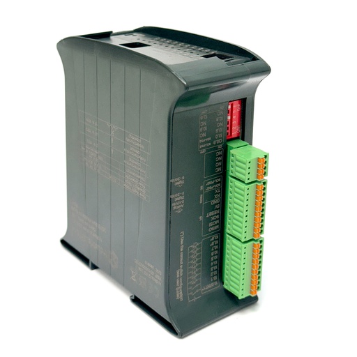
Ardbox Q
Modbus RTU with Arduino UNO Q in a DIN-rail PLC
Ardbox Q is the first industrial PLC with Arduino UNO Q. It has an RS-485 port for Modbus RTU, is programmed with the Arduino IDE and adds Debian Linux on a separate processor for data and dashboards.
FAQ about Modbus RTU on Arduino and ESP32 PLCs
Can one PLC be Modbus RTU master and slave at the same time?
Not on the same bus, because a Modbus RTU bus has one master. A PLC can be master on its RS-485 port and slave on another serial port, or slave on Modbus TCP over Ethernet. That is how a gateway works.
How many slaves can a PLC poll on one RS-485 bus?
Modbus allows addresses 1 to 247. RS-485 allows 32 unit loads per segment without a repeater, and more with 1/4 or 1/8 unit load transceivers. In practice the polling time limits it: each request waits for its answer or its timeout.
Which baud rate should I use?
The one the slaves support. 9600 and 19200 baud are the most common in meters and drives. Higher rates shorten the cycle but need a good cable and termination.
Does Modbus RTU work on the RS-232 port?
Yes. Create the master with ModbusRTUMaster master(RS232); and open the port with RS232.begin(baudrate, SERIAL_8E1). RS-232 connects only two devices over a short distance.
How do I read a 32-bit value or a float?
Read two consecutive registers and join them. The word order depends on the device: some send the high word first, others the low word. If the value looks wrong but there is no error, swap the two words.
What is the difference with Modbus TCP?
Modbus TCP carries the same function codes over Ethernet, with an IP address and a unit identifier instead of the slave address and the CRC. See Modbus TCP master on Arduino and ESP32 PLCs and Modbus RTU vs Modbus TCP vs OPC UA.