Case study · Modbus RTU and TCP · M-Duino 21
Many thermometers. One Modbus network.
PLCs read the probes on Modbus RTU and share the data on Modbus TCP.
Local PLCs read the thermometers. The main PLC reads the local PLCs.
One protocol family from the probe to the screen: Modbus RTU on the wires, Modbus TCP on the network.
This case describes a system to collect temperature readings with Industrial Shields equipment. It was first written in 2020 with the idea of a large register of body temperature. This page keeps its data path and applies it to temperature at many points. It does not name a customer or a site, and it does not publish any readings. This page follows one reading from a probe to a local PLC, then to the main PLC, and then to the server and the Panel PC.
The challenge
Temperature at many points must reach one place, and stay there.
The goal is a very extended register of temperature readings, so that the data can be used for statistical control. That means many thermometers, often far from each other, and one place where all the readings are stored and seen.
Many measuring points
Each point has a TQS3-M thermometer with a Modbus RTU output. The scheme of the case shows three thermometers and three local PLCs; it does not say how many thermometers each PLC reads.
Readings must travel
Local PLCs collect the readings of their thermometers and forward them to a main PLC. The case did it with Modbus RTU; with the M-Duino 21 this page uses Ethernet and Modbus TCP for that link.
Store every reading
A server system receives all the temperature data and works as the storage of the register.
See what happens
A Panel PC shows what the main PLC monitors and the data it receives from the other PLCs.
An open protocol
Modbus is open: no licence fee. It is widely supported by HMI and SCADA software, and many kinds of industrial equipment can be integrated with it.
How it works
Three steps: read the probe, collect, share.
Each step shows one link of the network. Press the buttons. The panels are illustrative simulations: addresses, register maps, frames, timeouts and temperatures are examples, not data from a site.
A local PLC asks each thermometer. Each one answers with its reading.
The TQS3-M thermometers send their data to the local PLCs over Modbus RTU, a binary protocol on a serial line. On Modbus RTU, only the master asks. A typical way to do it: the local PLC is the master of its own RS-485 bus and asks each probe in turn by its address. A probe that does not answer in time counts as a timeout. Pick a case and press Poll the probes.
- TQS3-M thermometers with a Modbus RTU output
- One RS-485 bus per local PLC (example)
- Each answer checked with its CRC
·
RS-485 bus of local PLC 1 (example)
Illustrative simulation. Example values, no data from a site. Example map: slave addresses 1 to 3, input register 0 = temperature × 10 (214 = 21.4 °C), 200 ms timeout. The TQS3-M register map is in its manual; the case does not publish it. The frames are real Modbus RTU frames, with the CRC computed on this page.
The main PLC reads the local PLCs over Ethernet.
The local PLCs forward the data to the main PLC. The case did it with Modbus RTU. An M-Duino 21 has one RS-485 port, and the local PLC already uses it for its thermometers, so the link that you can build today is Ethernet with Modbus TCP: the main PLC is the client and the local PLCs are servers. A typical way to do it: each local PLC keeps the readings of its probes in a few holding registers, and the main PLC reads them in a cycle. Pick a case and press Run one cycle.
- Main PLC as Modbus TCP client
- Local PLCs as Modbus TCP servers, with the readings in registers (example)
- A missing answer leaves stale values, not a gap (example)
·
Main PLC as Modbus TCP client (example)
Illustrative simulation. Example values, no data from a site. Example: local PLCs at 192.168.1.11, .12 and .13, unit 1, three holding registers each (function 03), 500 ms timeout. A local PLC that does not answer keeps its last values, marked as stale, and the main PLC asks again in the next cycle. The case linked the local PLCs and the main PLC with Modbus RTU and does not publish the cycle or the error handling.
Modbus TCP takes the data to the server and the Panel PC.
From the main PLC, the data go on Modbus TCP/IP over the Ethernet network. It works like Modbus RTU, but on TCP and IP. An Ethernet hub connects the main PLC to a server system, which stores all the temperature data, and to a Panel PC, which shows them. Pick a client and press Read 9 registers.
- Modbus TCP over Ethernet from the main PLC
- Server system stores every reading
- Panel PC shows the data and the state of the PLCs
·
Modbus TCP traffic (example)
Illustrative simulation. Example values, no data from a site. Example: the main PLC answers as a Modbus TCP server on port 502, unit 1, holding registers 0 to 8 (the nine readings of the three local PLCs). The server system and the Panel PC read them as clients. The case says the data go through an Ethernet hub to both; it does not publish the register map.
System architecture
How do Modbus RTU thermometers reach a server over Modbus TCP?
TQS3-M thermometers send their readings to local PLCs over Modbus RTU on RS-485. The local PLCs forward them to a main PLC. The case used Modbus RTU for that link; an M-Duino 21 has one RS-485 port, taken by the thermometers, so this page links the local PLCs and the main PLC over Ethernet with Modbus TCP. The main PLC then shares the data over Modbus TCP, through a hub, with a server system that stores every reading and with a Panel PC that shows them. On this page, all the PLCs are M‑Duino 21.
| Data | Between | Link | Purpose |
|---|---|---|---|
| Temperature reading | BetweenThermometer → local PLC | LinkModbus RTU | PurposeEach TQS3-M thermometer gives its reading to its local PLC |
| Readings of a group | BetweenLocal PLC → main PLC | LinkModbus TCP, Ethernet | PurposeThe main PLC reads the local PLCs. The case used Modbus RTU for this link |
| All the readings | BetweenMain PLC → server system | LinkModbus TCP, Ethernet | PurposeThe server stores the whole register of temperatures |
| Data and instructions | BetweenMain PLC ↔ Panel PC | LinkModbus TCP, Ethernet | PurposeThe Panel PC shows what the main PLC monitors and receives |
| Network | BetweenMain PLC, server, Panel PC | LinkEthernet hub | PurposeOne local network for the three devices |
Why it works
Simple links on the field. One network for the data.
No licence fee
Modbus is an open protocol. The PLCs, the server and the panel do not need a licence to use it.
Known by HMI and SCADA
Modbus is widely supported by HMI and SCADA software, so the server and the Panel PC can read the main PLC directly.
Many kinds of devices
Thermometers, PLCs and other industrial equipment with Modbus can share one network.
Right link at each level
Modbus RTU on serial wires near the probes. Modbus TCP on Ethernet where the server and the panel are.
One master per bus
On each Modbus RTU bus, one master asks and the slaves answer. The data flow is easy to follow and to test.
Built into the PLCs
The M-Duino PLCs have RS-485 and Ethernet. With the Industrial Shields Arduino libraries they work as Modbus RTU or TCP master or slave.
Hardware used
The same PLC at every level. A Panel PC to see the data.

M-DUINO ETHERNET PLC ARDUINO 21
An industrial PLC built around an original Arduino Mega 2560, with Ethernet, RS-485 and RS-232, for DIN rail. It is programmed with the Arduino IDE. In this case the same PLC does two jobs: as a local PLC it reads its thermometers over Modbus RTU and answers the main PLC over Modbus TCP; as the main PLC it collects the local PLCs and shares the data over Modbus TCP.
- Role
- Local PLC (thermometers) and main PLC (collect and share)
- I/O
- 13 inputs (6 analog 0-10 V), 8 outputs (3 analog/PWM 0-10 V)
- Communications
- Ethernet (W5500, 10/100 Mbit, RJ45), RS-485, RS-232, TTL serial, I2C, SPI
- Modbus
- RTU over RS-485 and TCP over Ethernet, master or slave
- Built in
- Real-time clock, microSD slot
- Programming
- Arduino IDE
- Power supply
- 12 to 24 Vdc
- Mounting
- DIN rail TS35, IP20
The text of the case names Industrial Shields PLCs based on Arduino and does not fix the model. The PLC photo of the original case is the M-Duino 21, which is still in the catalogue. This network uses almost no I/O, so a compact model like the M-Duino 21 fits. It has one RS-485 port and one RS-232 port: a local PLC uses RS-485 for its thermometers and Ethernet with Modbus TCP for the link to the main PLC. Another way, the RS-232 port with an RS-232 to RS-485 converter for a second Modbus RTU bus, is to be confirmed with our team for your model.
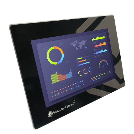
TouchBerry Pi Panel PC 10.1" FLEX
The screen of the network. An industrial Panel PC with a Raspberry Pi 4, on the same Ethernet network as the main PLC. As a Modbus TCP client it reads the data of the main PLC and shows the readings and the state of the PLCs.
- Role
- Visible interface of the main PLC
- Screen
- 10.1"
- Computer
- Raspberry Pi 4
- Link to the main PLC
- Ethernet, Modbus TCP
The case uses a Panel PC from Industrial Shields and does not fix the model. The TouchBerry Pi Panel PC 10.1" FLEX is one current option, and the CORE version is the standard configuration; the family also has 7" and 18.5" models. The case does not name the server system either: any computer or server on the network that reads Modbus TCP can store the register.
Questions about this case
How do Modbus RTU temperature sensors reach a Modbus TCP network?
Through a PLC that talks both. Here, local PLCs read TQS3-M thermometers over Modbus RTU on RS-485, and a main PLC reads the local PLCs over Ethernet with Modbus TCP. The main PLC shares the data over Modbus TCP with a server and a Panel PC. For the opposite direction, see a Modbus TCP to RTU gateway on an M-Duino PLC.
What is the difference between Modbus RTU and Modbus TCP?
Modbus RTU is a binary protocol on a serial line, usually RS-485, with one master and up to 247 slave addresses. Modbus TCP carries the same functions and registers over TCP/IP on Ethernet, on port 502, without the RTU CRC because TCP checks the data. Read Modbus RTU vs Modbus TCP vs OPC UA.
Can one local PLC read its thermometers and answer the main PLC?
Yes. On one Modbus RTU bus there is only one master, so a local PLC needs two links: one for its thermometers, one for the main PLC. An M-Duino 21 has one RS-485 port and one RS-232 port. The way you can build today: thermometers on RS-485 with Modbus RTU, and the link to the main PLC over Ethernet with Modbus TCP. The case used Modbus RTU for that link; doing it with the RS-232 port and an RS-232 to RS-485 converter is an alternative to confirm with our team.
How many thermometers fit on one RS-485 bus?
Modbus RTU allows slave addresses 1 to 247. The electrical limit comes from RS-485: 32 unit loads per segment, more with transceivers of 1/4 or 1/8 unit load, or with repeaters. Use a daisy chain, not a star, with 120 Ω termination at both ends. The scheme of the case shows three thermometers and three local PLCs; it does not say how many thermometers each PLC reads. Code: Modbus RTU with Arduino and ESP32 based PLCs.
How do the server and the Panel PC read the main PLC?
As Modbus TCP clients. The main PLC answers as a Modbus TCP server and keeps the readings in registers. The server stores them; the Panel PC shows them. A clear register map helps every client: see a Modbus TCP register map for a plant and Modbus TCP with Arduino and ESP32 based PLCs.
To see timeouts, CRC errors and stale values on a network like this one, try the Modbus network simulator.
Can the same network log body temperature?
Not with these thermometers. The original 2020 design had that goal, but the TQS3-M is an industrial probe on a cable: it measures what it touches. Screening people needs devices made and approved for that use. If such a device has a Modbus output, a PLC can read it like any other Modbus slave and add its readings to the register.
Similar network?
Tell us your measuring points. An engineer will answer.
Tell us how many points you measure, how far apart they are, which sensors or meters you have and where the data must go: a server, a SCADA, a screen. We will tell you which controllers fit and how to connect them.
- You get an answer from our technical team
- Modbus RTU and TCP layout for your sites
- Arduino, ESP32 or Raspberry Pi based PLCs