Case study · Proposed system · M-Duino 58
Wafers wait in a clean room. The PLC watches every corner.
Temperature, humidity and particles, point by point, with alarms.
Silicon wafers wait in a clean room before processing. Any drift in the room can damage them for good.
So the room is measured at several points, and every reading goes to two places.
This case describes the system that Industrial Shields proposed to a distribution company for the clean rooms of its customers in semiconductor manufacturing. The limits for temperature, humidity and particles come from the case. It does not name the company or its customers, and it does not publish results. The sensor points, timings and values in the panels are examples of a typical way to do it.
The challenge
The process is already strict. The storage room must be too.
Every step that makes a wafer already follows strict requirements. Before processing, the wafers wait in a clean room. The room must stay inside tight limits all the time: about 22 °C, between 18 and 26 °C, with 30 to 60 % relative humidity and a low particle count. A change in one corner of the room is enough to damage the products, and nobody should have to enter the room to check it.
Temperature at several points
One sensor near the door does not tell you what happens next to the racks. The room needs readings in different places.
Humidity and particles too
Humidity sensors and particle counters go around the room as well, so the results are reliable.
Alarms that someone sees
When a value leaves its band, the alarm must show on the panel outside the room and on the server that people watch from another place.
Data that is not lost
Every reading goes to a backup database server and to a cloud server, where it can be watched from another place.
Next step: the lights
The goals also include the lights of the room. A later option is to control them with a DALI system and switch them on and off on a schedule to use less energy.
How it works
Three jobs for one controller: measure, alarm, keep the data.
Each panel shows one job. Press the buttons and move the controls. The panels are illustrative simulations: the limits are the ones of the case, but the points, timings and values are examples, not data from a real room.
Several points, each with its own band.
Sensors in different places of the room read temperature and humidity. The PLC checks every point against the band of the case, not only the room average. When a door is held open, one point can leave the band while the average still looks fine. Pick a scenario and watch the four points. To run a full day of climate control with alarms in a closed room, open the greenhouse climate simulator and its mushroom room (it runs on ESP32 PLCs; the band logic is the same).
- Temperature and humidity at several points
- Each point checked on its own: 18 to 26 °C, 30 to 60 % RH
- An alarm when one point leaves its band
Events (example)
Illustrative simulation. Example values, not data from a room. Example points and values, shown faster than real time. The bands are the ones of the case: 18 to 26 °C and 30 to 60 % RH. A typical way to do it: the PLC checks each point on its own, not only the average.
A particle alarm that one spike does not trigger.
A particle counter reads the air. The limit of the case is 80,000 particles in 0.028 m³. The PLC raises the alarm only when the level stays above the limit, turns on a beacon, and tells the panel and the server. A person acknowledges it on the panel, outside the room. Move the level, add one spike, and acknowledge.
- Particle limit: 80,000 in 0.028 m³
- Confirmed over several samples
- Acknowledged from outside the room
Particle events (example)
Illustrative simulation. Example values, not data from a room. Example samples, one every few seconds here. The limit is the one of the case: 80,000 particles in 0.028 m³. A typical way to do it: the alarm starts after 3 samples in a row above the limit, so one spike does not stop the work, and it stays on until the level is back under the limit.
Two copies of every reading, even when a link is down.
The PLC sends every reading over Ethernet to a backup database server and to a cloud server, where the room can be watched from another place. If the cloud link or the whole network is down, the PLC keeps the records and sends them when the link is back. Cut the network or the cloud link and watch the counters.
- A backup database server on the plant network
- A cloud server for remote monitoring
- Records kept on microSD while a link is down
Data events (example)
Illustrative simulation. Example values, not data from a room. Example records, one per second here. A typical way to do it: each record has a time from the real-time clock of the PLC. When a link is down, the PLC keeps the records on its microSD card and sends them later. See offline-first data logging with an SD card (the example runs on an ESP32 PLC; the pattern is the same).
System architecture
How do you monitor a semiconductor clean room with a PLC?
One industrial PLC is the master of all the sensors. Temperature, humidity and particle sensors go at several points of the room. The case chooses the bus by device and distance: I2C for sensors close to the controller, RS-485 with Modbus RTU for sensors spread across the room. A typical way to do it: a digital output drives an alarm beacon. A TouchBerry Pi panel outside the clean room shows the values and the alarms. Over Ethernet (the case also allows Wi-Fi), the PLC sends every reading to a backup database server and to a cloud server. DALI lights are a later step.
| Signal | Between | Type | Purpose |
|---|---|---|---|
| Temperature, points A to D | BetweenSensors in the room → PLC | TypeRS-485, Modbus RTU | PurposeBand of the case: 18 to 26 °C, ideal 22 °C |
| Relative humidity, points A to D | BetweenSensors in the room → PLC | TypeRS-485, Modbus RTU | PurposeBand of the case: 30 to 60 % |
| Sensors close to the cabinet | BetweenSensors → PLC, short cable | TypeI2C | PurposeReadings next to the controller. I2C is for short distances only |
| Particles | BetweenParticle counter → PLC | TypeRS-485, Modbus RTU | PurposeLimit of the case: 80,000 particles in 0.028 m³ |
| Alarm beacon and horn | BetweenPLC → beacon | TypeDigital out | PurposeLocal alarm when a value leaves its band |
| Operator screen | BetweenPLC ↔ TouchBerry Pi 10.1", outside the room | TypeEthernet | PurposeValues per point, alarms, acknowledge |
| Backup copy | BetweenPLC → database server | TypeEthernet | PurposeEvery reading, with the time of the real-time clock |
| Remote copy | BetweenPLC → cloud server | TypeEthernet, Internet | PurposeWatch the room from another place |
| Lights (later step) | BetweenDALI version of the PLC → DALI bus → luminaires | TypeDALI | PurposeSwitch on and off on a schedule to use less energy |
Why this design
Measure where the risk is. Keep the data twice.
Readings where the products are
Any variation can damage the wafers, so one sensor is not enough. Several points show a bad corner that the average hides.
The right bus for each distance
I2C works on short cables next to the controller. RS-485 with Modbus RTU reaches sensors across the room and beyond, many devices on one pair of wires. See a Modbus RTU example on an M-Duino PLC.
Room on the controller
The M-Duino 58 has 36 inputs and 22 outputs, Ethernet, RS-485 and I2C. The monitoring uses few of them, so new points fit on the same controller.
A panel outside the room
People check the values and acknowledge alarms on the TouchBerry Pi panel, outside the clean room. They do not need to enter to read a sensor.
Two copies of the data
A backup database server on the plant network and a cloud server. If one of them stops, the other still has the records. The real-time clock and the microSD card of the PLC keep the time and the records when a link is down.
Code that you own
The PLC is programmed with the Arduino IDE and open source libraries. You get the code of the application, so you can check it and change it later.
Proposed hardware
One controller for the sensors. One panel outside the room.
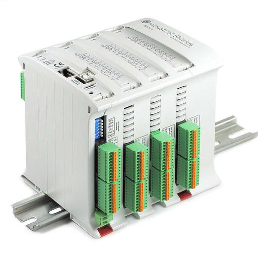
M-DUINO ETHERNET PLC ARDUINO 58
An industrial PLC built around an original Arduino Mega 2560, with 36 inputs and 22 outputs, Ethernet, RS-485, RS-232, I2C, a real-time clock and a microSD slot, for DIN rail. In this case it is the master of all the sensors, drives the alarm and sends the data.
- Role
- Master of the sensors, alarms, data to the database and the cloud
- Inputs
- 36: 16 analog/digital (0-10 V, 10-bit), 20 digital optoisolated (5 to 24 Vdc)
- Outputs
- 22: 8 analog/digital/PWM (0-10 V), 14 digital optoisolated (5 to 24 Vdc)
- Comms
- Ethernet 10/100 (W5500), RS-485, RS-232, TTL serial, I2C, SPI
- Built in
- Real-time clock, microSD slot
- Programming
- Arduino IDE with the Industrial Shields boards package
- Power and mounting
- 12 to 24 Vdc, DIN rail TS35, IP20, 0 to 60 °C
The original case shows pictures of the M-Duino 58 and the M-Duino 57R and does not name the exact model. The M-Duino 58 fits what the case asks for. The case sends the data over Ethernet or Wi-Fi. The M-Duino 58 has Ethernet on board; for Wi-Fi, the family has Wi-Fi & BLE versions (see the M-Duino Wi-Fi & BLE family datasheet), and for the DALI lights, DALI versions (M-Duino DALI family datasheet).
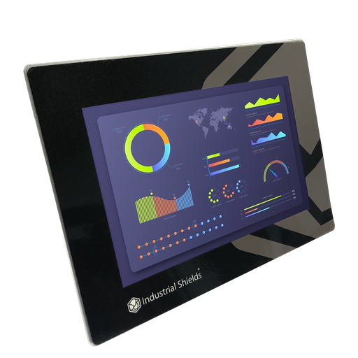
TouchBerry Pi Panel PC 10.1" FLEX
The touch screen outside the clean room: a Raspberry Pi 4 behind a 10.1" capacitive touchscreen, on Ethernet to the PLC. It shows the values of each point and the alarms, and people acknowledge the alarms here.
- Role
- Values per point, alarms, acknowledge, outside the room
- Screen
- 10.1" IPS, 1280 x 800, capacitive, 900 nits
- Front
- IP20 or IP65 on the FLEX version
- Software
- Linux, preinstalled: Node-RED dashboard, Python or a browser
- Comms
- Gigabit Ethernet, 4 x USB, one serial port (RS-485, RS-232 or TTL)
- Power
- 12 to 24 Vdc, UPS for safe shutdown
The original case links to the 10.1" Panel PC. The current model is the TouchBerry Pi Panel PC 10.1" FLEX.
Questions about this case
What conditions does a semiconductor wafer storage room need?
In this case: an ideal temperature of 22 °C, always between 18 and 26 °C, relative humidity between 30 and 60 %, and no more than 80,000 particles in 0.028 m³ of air. These are the limits of this case. Each plant sets its own limits for its products and its process.
How many sensors does a clean room need, and where?
More than one. Any variation can damage the products, and one sensor near the door does not show what happens next to the racks. A typical way to do it: put points near the door, near the supply air, next to the stored wafers and in the far corner, and check each point against its band. The PLC raises the alarm when one point leaves its band, even if the average is fine.
I2C or RS-485 with Modbus RTU for clean room sensors?
It depends on the device and the distance, as the case says. I2C is a short-distance bus for sensors close to the controller. RS-485 with Modbus RTU is a differential bus for longer cables: up to about 1,200 m at low baud rates and up to 32 unit loads on one segment. The M-Duino 58 has both. See the I2C bus on an Arduino based PLC and a Modbus RTU example on an M-Duino PLC.
How does 80,000 particles in 0.028 m³ compare to the ISO 14644-1 classes?
0.028 m³ is about one cubic foot. 80,000 particles in 0.028 m³ are about 2.8 million particles per m³. ISO 14644-1 classifies clean rooms by particles per m³ for each particle size: ISO Class 8 allows 3,520,000 particles of 0.5 µm and larger per m³, and ISO Class 7 allows 352,000. The case does not give the particle size, so check the size and the class with your process.
What happens to the data if the network goes down?
The case sends every reading to two places: a backup database server and a cloud server. A typical way to do it: if a link is down, the PLC keeps the records on its microSD card, with the time of its real-time clock, and sends them when the link is back. An alarm history can also live in a database next to the panel. See alarm history in MySQL with Node-RED.
Can the same PLC control the clean room lights with DALI?
Yes, as a later step, with a DALI version of the M-Duino family. The M-Duino 58 Ethernet used here has no DALI bus, so the lights need the DALI version or a separate DALI controller. The case proposes DALI to switch the lights on and off on a schedule and use less energy. DALI (IEC 62386) is a two-wire lighting bus with up to 64 addressable devices per line. The DALI versions are described in the M-Duino DALI family datasheet.
Download the case study
4-page PDF with the challenge, the logic, the architecture and the hardware. No form required.
Monitoring a controlled room?
Tell us about your room and your limits. An engineer will answer.
Tell us the size of the room, the variables and their limits, how many points you want to measure and where the data must go. We will propose the buses, the controller and the panel.
- You get an answer from our technical team
- Points, buses and alarms for your room
- Arduino, ESP32 or Raspberry Pi based PLCs