Success story · FACE-IT · Ny-Ålesund, Svalbard
12 Arctic tanks, four water conditions. M-Duino 42+ PLCs keep each on target.
In Ny-Ålesund, in the Svalbard archipelago (Norway), FACE-IT studies warmer, fresher and more turbid Arctic water.
Arctic water gets warmer, fresher and more turbid.
FACE-IT recreates it in nine of twelve tanks.
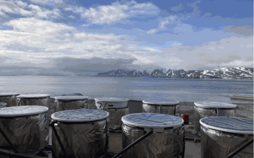
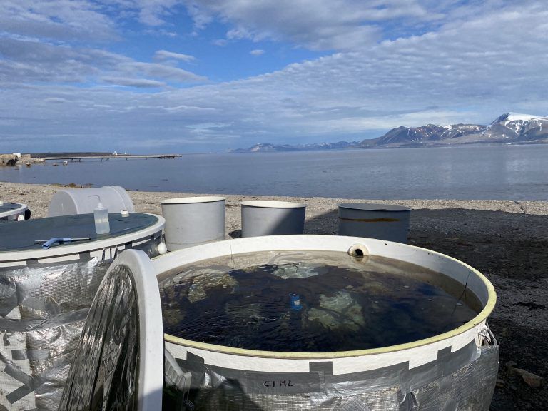
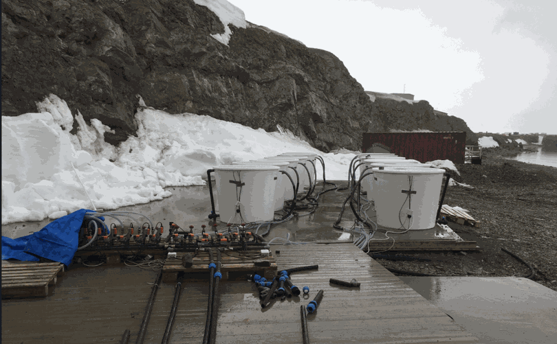
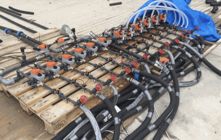
FACE-IT studies the effects of global warming on Arctic fjords. In Ny-Ålesund, in the Svalbard archipelago (Norway), it installed 12 mesocosms: outdoor tanks under controlled conditions. Three are control mesocosms. The experiment runs in the other nine. Industrial Shields proposed several M-Duino 42+ PLCs. Each PLC regulates three mesocosms with two valves per tank and reads sensors on an RS-485 bus. The master PLC logs the data and talks to a control computer over WebSocket.
From the field
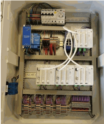
The tanks, the valves and the cabinet.
Real photos from the original case, with the credits published with it.
The challenge
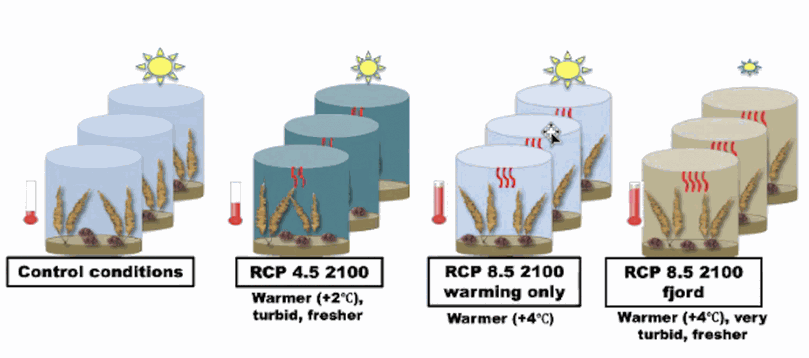
Four water conditions. Three tanks each.
FACE-IT wants to study the effects of global warming: higher water temperature, lower salinity and turbidity. The design of the experiment has four groups of three mesocosms. RCP 4.5 and RCP 8.5 are greenhouse gas scenarios of the IPCC, here for the year 2100. Each tank must stay on the conditions of its group.
Control conditions
Three mesocosms run under control conditions. They are the reference for the other nine.
RCP 4.5, 2100
Warmer water (+2 °C), turbid and fresher.
RCP 8.5, 2100, warming only
Warmer water (+4 °C). Only the temperature changes.
RCP 8.5, 2100, fjord
Warmer water (+4 °C), very turbid and fresher.
The customer: FACE-IT
The rapid loss of sea ice is a clear sign of the global climate crisis. Glacial fronts and sea ice are hotspots of biodiversity. Its team works with mesocosms in Ny-Ålesund, in the Svalbard archipelago (Norway). The overall objective of FACE-IT is to enable adaptive co-management of social-ecological fjord systems in the Arctic, in the face of rapid changes in the cryosphere and biodiversity. It asked for a PLC that is easy to program and easy to connect to sensors.
How it works
Three loops: regulate, measure, supervise.
The PLCs run three jobs: hold each tank on its scenario, read the water sensors of three tanks, and send the data to the control computer. The facts come from the case. The behaviour in the panels is an illustrative simulation.
Two valves hold each tank on its scenario.
Each mesocosm has its own 3-way temperature control valve and its own 2-way fresh water control valve. Both take an analog signal from the PLC. More fresh water means lower salinity. The sensors give the PLC the real water values to compare with the target. The case does not publish the set points or the control algorithm. A typical way to do it: one PI loop per valve.
- 3-way valve: water temperature
- 2-way valve: fresh water, so salinity
- Analog signal from the PLC to each valve
- Set points and algorithm: not published
Illustrative simulation. Example set points, scaled times, no program from the installation. The case does not say how the turbidity is produced. It is measured on the RS-485 bus.
Related: zone climate control in the greenhouse climate simulator
Each PLC regulates three mesocosms.
The work is split: each PLC regulates three mesocosms. With two valves per tank, that is six analog valve signals per PLC. Multiple sensors on an RS-485 bus measure the temperature, the salinity and the turbidity. The case does not publish the bus protocol, the sensor models or the wiring. The panel polls the bus with example frames.
- 3 mesocosms per PLC
- 6 analog valve signals per PLC, 2 per tank
- RS-485 bus: temperature, salinity, turbidity
- Protocol and addresses: not published
RS-485 bus (example frames)
Example frames. A0.5 to A1.7 are the analog outputs of the M-Duino 42+; the pin for each valve is an example. The case does not publish the bus protocol or the sensor addresses.
The master PLC logs. The computer supervises.
The master PLC logs the data on a µSD card and talks to a control computer. The PLCs connect to the computer through their RJ45 ports, with the WebSocket protocol. On the computer, an application written in C# monitors and controls the experiment.
- Master PLC: data log on a µSD card
- PLCs to computer: RJ45 (Ethernet), WebSocket
- C# application: monitor and control
- Message format and interval: not published
WebSocket (example messages)
Example messages. The case does not publish the message format or the logging interval.
System architecture
How do M-Duino 42+ PLCs regulate 12 Arctic mesocosms?
Each PLC drives two valves per tank with analog signals and reads the water sensors on an RS-485 bus. Twelve mesocosms at three per PLC make four PLCs. The master PLC logs to a µSD card. All PLCs reach the control computer through RJ45 ports with WebSocket, and a C# application monitors and controls the experiment.
| Flow | Between | Type | Purpose |
|---|---|---|---|
| Water temperature, salinity, turbidity | BetweenSensors → PLCs | TypeRS-485 bus | PurposeMeasure the water in each mesocosm |
| Temperature valve | BetweenPLC → 3-way valve | TypeAnalog signal | PurposeSets the water temperature of each mesocosm |
| Fresh water valve | BetweenPLC → 2-way valve | TypeAnalog signal | PurposeSets the fresh water to each mesocosm |
| Data log | BetweenMaster PLC → µSD card | TypeLocal storage | PurposeKeeps the experiment data in the cabinet |
| Supervision | BetweenPLCs ↔ control computer | TypeWebSocket, RJ45 | PurposeData to the computer, commands to the PLCs |
| Interface | BetweenControl computer | TypeC# application | PurposeMonitor and control the experiment |
Why it works
Why Industrial Shields won the project.
Arduino IDE programming
The case gives two factors for the choice. The first is the programming platform: M-Duino PLCs are programmed with the Arduino IDE and the Industrial Shields boards package.
Flexible programming
The second factor in the case is the flexibility of programming. Here one PLC model reads the RS-485 sensors, drives the analog valve signals and talks WebSocket to the computer.
Room to grow
The PLCs are modular. The original case page notes that the specifications can be extended later.
Hardware used
M-Duino 42+ PLCs regulate the mesocosms.
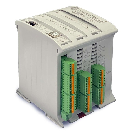
M-Duino Ethernet PLC Arduino 42
An industrial PLC built on an original Arduino Mega 2560, with 26 inputs and 16 outputs, Ethernet, RS-485 and RS-232, for DIN rail. In this experiment each unit regulates three mesocosms: it drives two analog valve signals per tank and reads the sensors on the RS-485 bus.
- Inputs
- 26: 12 analog/digital (0-10 V, 10-bit), 14 digital optoisolated, 4 with interrupt
- Outputs
- 16: 6 analog/digital/PWM (0-10 V, 8-bit), 10 digital optoisolated
- Ethernet
- W5500, 10/100 Mbit, RJ45
- Serial and buses
- RS-485, RS-232, TTL, I2C, SPI
- Built in
- Real-time clock, microSD slot
- Power supply
- 12 to 24 Vdc
- Mounting
- DIN rail TS35, IP20
The case PDF names the M-Duino 42+. The 2021 case page says M-Duino 42. This product page sells the current version, the M-Duino 42+. The case does not publish any extra modules.
Questions about this case
What is a mesocosm?
A mesocosm is a controlled outdoor experimental setup that investigates the natural environment. It holds key parts of an ecosystem and shows the basic processes that take place in it. In this case, FACE-IT installed 12 mesocosms on the shore in Ny-Ålesund, in the Svalbard archipelago (Norway).
Who runs this experiment and what does it study?
FACE-IT. Its overall objective is to enable adaptive co-management of social-ecological fjord systems in the Arctic, in the face of rapid changes in the cryosphere and biodiversity. The experiment studies the effects of global warming on the water: higher temperature, lower salinity and turbidity.
What do RCP 4.5 and RCP 8.5 mean here?
RCP means Representative Concentration Pathway, a greenhouse gas scenario used by the IPCC. RCP 8.5 is the higher emission pathway. The design of the case has three groups for the year 2100: RCP 4.5 (warmer by 2 °C, turbid, fresher), RCP 8.5 warming only (warmer by 4 °C) and RCP 8.5 fjord (warmer by 4 °C, very turbid, fresher). Three more mesocosms run under control conditions.
How does the PLC control the temperature and the salinity of each tank?
Each mesocosm has a 3-way temperature control valve and a 2-way fresh water control valve, both on an analog signal from the PLC. More fresh water means lower salinity. Sensors on an RS-485 bus measure temperature, salinity and turbidity. The set points and the control algorithm are not published. Read more: Basics about analog outputs of an industrial PLC.
How do the PLCs talk to the control computer?
Through their RJ45 Ethernet ports, with the WebSocket protocol. A WebSocket keeps one TCP connection open in both directions, so the computer receives data and sends commands on the same link. The master PLC also logs the data on a µSD card (see Basics with SD card in an industrial PLC). On the computer, a C# application monitors and controls the experiment.
Can one M-Duino 42+ drive the valves of three tanks?
In this case each PLC regulates three mesocosms. With two valves per tank, that is six analog signals. The M-Duino 42+ has six analog outputs (0-10 V) and RS-485 for the sensor bus. The case does not publish the signal range of the valves, so check that your valve actuators accept 0-10 V, or add a signal converter. Read more: RS-485 with Arduino and ESP32 based PLCs.
Download the success story
4-page PDF with the challenge, the logic, the architecture and the hardware. No form required.
Similar project?
Tell us your tanks and your variables. An engineer will answer.
Tell us how many tanks or zones you regulate, which variables you measure, which valves or pumps you drive and where the data must go: a PC application, a SCADA or a database. We will tell you which controller fits and how to wire it.
- You get an answer from our technical team
- Analog outputs, buses and I/O count for your setup
- Arduino, ESP32 or Raspberry Pi based PLCs