Introduction
In the Arduino automation area, the Modbus RTU protocol is a means of communication that allows the exchange of data between programmable logic controllers (industrial PLC controller Arduino) and computers.
Electronic devices can exchange information through serial lines using the Modbus protocol.
In this post, you are going to learn how Modbus RTU works!
Index
1. What is Modbus RTU?
2. How does Modbus RTU work?
3. Modbus general frame structure
4. Modbus Function Code
5. Modbus Object Types
6. Modbus Data Format
6.1. (0x01) Read Coils
6.2. (0x02) Read discrete inputs
6.3. (0x03) Read Holding Registers
6.4. (0x04) Read Input Register
6.5. (0x05) Write Single Coil
6.6. (0x06) Write Single Register
6.7. (0x0F) Write Multiple Coils
6.8. (0x10) Write Multiple Holding Register
7. Creating our Modbus RTU message
8. Software
1. What is Modbus RTU
Modbus is a communication protocol located at levels 1, 2 and 7 of the OSI Model, based on the master/slave architecture, designed in 1979 by Modicon for its range of PLCs.
Converted into a de facto standard communications protocol in the industry, let’s see some of the main features:
- Designed with its use in industrial applications in mind
- It is public and free
- It is easy to implement and requires little development.
- Handles blocks of data without assuming restrictions
- Each of the messages includes redundant information that ensures its integrity at reception.
- The basic Modbus commands allow you to control an RTU device to modify the value of any of its registers or to request the content of these registers.
2. How does MODBUS RTU work
Modbus RTU is the most common implementation available for Modbus.
Modbus RTU is used in serial communication and makes use of a compact, binary representation of the data for protocol communication.
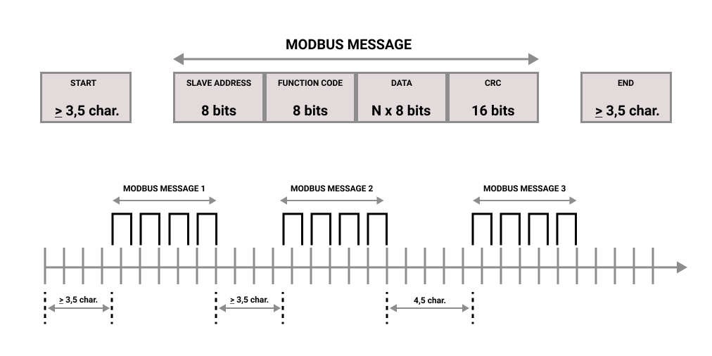
Modbus messages are divided by idle periods as you can see in the picture below.

Each device on a Modbus communication has a unique address.
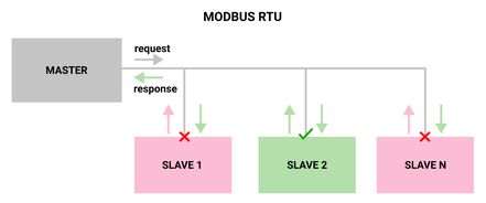
The Modbus RTU works by RS-485 which is a single cable multi-drop network, only the node assigned as the Master may initiate a command. All the other devices are slaves and answer requests and commands.
A Modbus command contains the Modbus address of the device it is intended for. Only the addressed device will respond and act on the command, even though other devices might receive it.
Also, it is important to say that all Modbus commands contain checksum information to allow the recipient to detect transmission errors.
Let's give an example! Imagine that we have a Modbus serial network, where there is a master and up to 31 slaves, each with a unique slave address.
The master only wants to send a message to slave number 2 requesting the value of 6 input registers.
So, the master would send a message and all the slaves would receive the message, but only slave number 2 will respond and act on the command, even though other devices might receive it.
With this example, we are going to create a Modbus RTU message along with this post.
Modbus message at the moment: 02 (slave address)

3. Modbus general frame structure
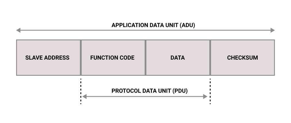
The Modbus RTU Application Data Unit (ADU) consists of the shown elements:

Of these, The Function Code and Data constitute the Protocol Data Unit (PDU)
4. Modbus Function Code
MODBUS is a request/reply protocol and offers services specified by function codes. MODBUS function codes are elements of MODBUS request/reply PDUs.
The function code field of a MODBUS data unit is coded in one byte. Valid codes are in the range of 1 to 255 decimal (the range 128 – 255 is reserved and used for exception responses). When a message is sent from a Client to a Server device the function code field tells the server what kind of action to perform. Function code "0" is not valid. Sub-function codes are added to some function codes to define multiple actions.
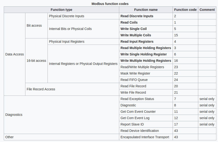
Below you can find the list of function codes and their functions:

5. Modbus Object Types
In Modbus, the data types can be divided majorly in two types: Coils and Registers. The coils can be understood as digital as can only be either ON (1) or OFF (0). Some coils can represent inputs and some as outputs.
The Registers are of 16 bits ( 2 bytes) unsigned registers and therefore can have values from 0 to 65535 (0 to FFFF). Though it has its limitations such as it cannot represent negative numbers, floating-point numbers, or values with representation greater than 65535. The below table summarises the object types.
The four primary tables are the following:
| PRIMARY TABLES | OBJECT TYPE | TYPE OF | COMMENTS |
| Discrete inputs (Inputs) | Single bit | Read-Only | This type of data be provided by an I/O system. |
| Coils (Outputs) | Single bit | Read-Write | This type of data can be alterable by an application. |
| Input Registers (Inputs) | 16-bit word | Read-Only | This type of data can be provided by an I/O system. |
| Holding Registers (Outputs) | 16-bit word | Read-Write | This type of data can be alterable by an application program. |
6. Modbus Data Format
Function codes descriptions
Modbus requests and responses contain an Application Data Unit (ADU) which contains a Protocol Data Unit (PDU).
Let's see how they are.

6.1. (0x01) Read Coils
This function code is used to read from 1 to 2000 contiguous status of coils in a remote device.
The coils in the response message are packed as one coil per bit of the data field. Status is indicated as 1: ON and 0: OFF. The LSB of the first data byte contains the output addressed in the query. The other coils follow toward the high order end of this byte, and from low order to high order in subsequent bytes.
Request
| Function Code | 1 Byte | 0x01 |
| Starting Address | 2 Bytes | 0x0000 to 0xFFFF |
| Quantity of coils | 2 Bytes | 1 to 2000 (0x7D0) |
Response
| Function Code | 1 Byte | 0x01 |
| Byte count | 1 Byte | N* |
| Coil status | n Bytes | n = N or N+1 |
*N = Quantity of Outputs / 8, if the remainder is different of 0 => N = N+1
Example of a request to read discrete outputs 20 –38:
| Request | Response | ||
| Field Name | Hex | Field Name | Hex |
| Function | 01 | Function | 01 |
| Starting Address Hi | 00 | Byte Count | 03 |
| Starting Address Lo | 13 | Outputs status 27-20 | CD |
| Quantity of Outputs Hi | 00 | Outputs status 35-28 | 6B |
| Quantity of Outputs Lo | 13 | Outputs status | 05 |
*The CRC must be calculated.
6.2. (0x02) Read Discrete Inputs
This function code is used to read from 1 to 2000 contiguous status of discrete inputs in a remote device.
The Request PDU specifies the starting address, i.e. the address of the first input specified, and the number of inputs. In the PDU Discrete Inputs are addressed starting at zero. Therefore Discrete inputs numbered 1-16 are addressed as 0-15.
The discrete inputs in the response message are packed as one input per bit of the data field. Status is indicated as 1= ON; 0= OFF. The LSB of the first data byte contains the input addressed in the query. The other inputs follow toward the high order end of this byte, and from low order to high order in subsequent bytes.
Request
| Function Code | 1 Byte | 0x02 |
| Starting Address | 2 Bytes | 0x0000 to 0xFFFF |
| Quantity of Inputs | 2 Bytes | 1 to 2000 (0x7D0) |
Response
| Function Code | 1 Byte | 0x02 |
| Byte count | 1 Byte | N* |
| Input status | N* x 1 Byte |
Example of a request to read discrete inputs 197 – 218:
| Request | Response | ||
| Field Name | Hex | Field Name | Hex |
| Function | 02 | Function | 02 |
| Starting Address Hi | 00 | Byte Count | 03 |
| Starting Address Lo | C4 | Outputs status 27-20 | AD |
| Quantity of Outputs Hi | 00 | Outputs status 35-28 | DB |
| Quantity of Outputs Lo | 16 | Outputs status | 35 |
6.3. (0x03) Read Holding Registers
This function code is used to read the contents of a contiguous block of holding registers in a remote device. The Request PDU specifies the starting register address and the number of registers. In the PDU Registers are addressed starting at zero. Therefore registers numbered 1-16 are addressed as 0-15.
The register data in the response message are packed as two bytes per register, with the binary contents right justified within each byte. For each register, the first byte contains the high order bits and the second contains the low order bits.
Request
| Function Code | 1 Byte | 0x03 |
| Starting Address | 2 Bytes | 0x0000 to 0xFFFF |
| Quantity of Registers | 2 Bytes | 1 to 125 (0x7D0) |
Response
| Function Code | 1 Byte | 0x03 |
| Byte count | 1 Byte | 2 x N* |
| Register value | N* x 2 Bytes |
*N = Quantity of Registers
Example of a request to read registers 108 – 110:
| Request | Response | ||
| Field Name | Hex | Field Name | Hex |
| Function | 03 | Function | 03 |
| Starting Address Hi | 00 | Byte Count | 06 |
| Starting Address Lo | 6B | Register value Hi (108) Register value Lo (108) | 02 2B |
| No. of Registers Hi | 00 | Register value Hi (109) Register value Lo (109) | 00 00 |
| No. of Registers Lo | 03 | Register value Hi (110) Register value Lo (110) | 00 64 |
6.4. (0x04) Read Input Registers
This function code is used to read from 1 to 125 contiguous input registers in a remote device. The Request PDU specifies the starting register address and the number of registers. In the PDU Registers are addressed starting at zero. Therefore input registers numbered 1-16 are addressed as 0-15.
The register data in the response message are packed as two bytes per register, with the binary contents right justified within each byte. For each register, the first byte contains the high order bits and the second contains the low order bits.
Request
| Function Code | 1 Byte | 0x04 |
| Starting Address | 2 Bytes | 0x0000 to 0xFFFF |
| Quantity of Input Registers | 2 Bytes | 0x0001 to 0x007D |
Response
| Function Code | 1 Byte | 0x04 |
| Byte count | 1 Byte | 2 x N* |
| Input Registers | N* x 2 Bytes |
*N = Quantity of Input Registers
Example of a request to read input register 9
| Request | Response | ||
| Field Name | Hex | Field Name | Hex |
| Function | 04 | Function | 04 |
| Starting Address Hi | 00 | Byte Count | 02 |
| Starting Address Lo | 08 | Input Reg. 9 Hi | 00 |
| Quantity of Input Reg. Hi | 00 | Input Reg. 9 Lo | 0A |
| Quantity of Input Reg. Lo | 01 |
6.5. (0x05) Write Single Coil
This function code is used to write a single output to either ON or OFF in a remote device.
The requested ON/OFF state is specified by a constant in the request data field. A value of FF00 hex requests the output to be ON. A value of 00 00 requests it to be OFF. All other values are illegal and will not affect the output.
The Request PDU specifies the address of the coil to be forced. Coils are addressed starting at zero. Therefore coil numbered 1 is addressed as 0. The requested ON/OFF state is specified by a constant in the Coil Value field. A value of 0XFF00 requests the coil to be ON. A value of 0X0000 requests the coil to be off. All other values are illegal and will not affect the coil.
The normal response is an echo of the request, returned after the coil state has been written.
Request
| Function Code | 1 Byte | 0x05 |
| Output Address | 2 Bytes | 0x0000 to 0xFFFF |
| Output value | 2 Bytes | 0x0000 to 0xFF00 |
Response
| Function Code | 1 Byte | 0x05 |
| Byte count | 2 Byte | 0x0000 to 0xFFFF |
| Input Registers | 2 Bytes | 0x0000 or 0xFF00 |
Example of a request to write Coil 173 ON:
| Request | Response | ||
| Field Name | Hex | Field Name | Hex |
| Function | 05 | Function | 05 |
| Starting Address Hi | 00 | Output Address Hi | 00 |
| Starting Address Lo | AC | Output Address Lo | AC |
| Quantity of Input Reg. Hi | FF | Output Value Hi | FF |
| Quantity of Input Reg. Lo | 00 | Output Value Lo | 00 |
6.6. (0x06) Write Single Register
This function code is used to write a single holding register in a remote device.
The Request PDU specifies the address of the register to be written. Registers are addressed starting at zero. Therefore register numbered 1 is addressed as 0.
The normal response is an echo of the request, returned after the register contents have been written.
Request
| Function Code | 1 Byte | 0x06 |
| Register Address | 2 Bytes | 0x0000 to 0xFFFF |
| Register value | 2 Bytes | 0x0000 to 0xFFFF |
Response
| Function Code | 1 Byte | 0x06 |
| Register Address | 2 Byte | 0x0000 to 0xFFFF |
| Register value | 2 Bytes | 0x0000 or 0xFF00 |
Example of a request to write register 2 to 00 03 hex:
| Request | Response | ||
| Field Name | Hex | Field Name | Hex |
| Function | 06 | Function | 06 |
| Starting Address Hi | 00 | Output Address Hi | 00 |
| Starting Address Lo | 01 | Output Address Lo | 01 |
| Quantity of Input Reg. Hi | 00 | Output Value Hi | 00 |
| Quantity of Input Reg. Lo | 03 | Output Value Lo | 03 |
6.7. (0x0F) Write Multiple Coils
This function code is used to force each coil in a sequence of coils to either ON or OFF in a remote device. The Request PDU specifies the coil references to be forced. Coils are addressed starting at zero. Therefore coil numbered 1 is addressed as 0.
The requested ON/OFF states are specified by contents of the request data field. A logical ' 1' in a bit position of the field requests the corresponding output to be ON. A logical '0' requests it to be OFF.
The normal response returns the function code, starting address, and quantity of coils forced.
Request
| Function Code | 1 Byte | 0x0F |
| Starting Address | 2 Bytes | 0x0000 to 0xFFFF |
| Quantity of Outputs | 2 Bytes | 0x0001 to 0x07B0 |
| Byte Count | 1 Byte | N* |
| Outputs Value | N* x 1 Byte |
*N = Quantity of Outputs / 8, if the remainder is different of 0 => N = N+1
Response
| Function Code | 1 Byte | 0x0F |
| Starting Address | 2 Byte | 0x0000 to 0xFFFF |
| Quantity of Outputs | 2 Bytes | 0x0001 or 0x07B0 |
Example of a request to write register 2 to 00 03 hex:
| Request | Response | ||
| Field Name | Hex | Field Name | Hex |
| Function | 0F | Function | 0F |
| Starting Address Hi | 00 | Starting Address Hi | 00 |
| Starting Address Lo | 13 | Starting Address Lo | 13 |
| Quantity of Outputs Hi | 00 | Quantity of Outputs Hi | 00 |
| Quantity of Outputs Lo | 0A | Quantity of Outputs Lo | 0A |
| Byte Count | 02 | ||
| Outputs Value Hi | CD | ||
| Outputs Value Lo | 01 |
6.8. (0x10) Write Multiple Registers
This function code is used to write a block of contiguous registers (1 to 123 registers) in a remote device.
The requested written values are specified in the request data field. Data is packed as two bytes per register.
The normal response returns the function code, starting address, and quantity of registers written.
Request
| Function Code | 1 Byte | 0x10 |
| Starting Address | 2 Bytes | 0x0000 to 0xFFFF |
| Quantity of Registers | 2 Bytes | 0x0001 to 0x007B |
| Byte Count | 1 Byte | 2 x N* |
| Registers Value | N* x 2 Bytes | value |
*N = Quantity of Registers
Response
| Function Code | 1 Byte | 0x10 |
| Starting Address | 2 Byte | 0x0000 to 0xFFFF |
| Quantity of Registers | 2 Bytes | 0x123 or (0x7B) |
Example of a request to write two registers starting at 2 to 00 0A and 01 02 hex:
| Request | Response | ||
| Field Name | Hex | Field Name | Hex |
| Function | 10 | Function | 10 |
| Starting Address Hi | 00 | Starting Address Hi | 00 |
| Starting Address Lo | 01 | Starting Address Lo | 01 |
| Quantity of Registers Hi | 00 | Quantity of Outputs Hi | 00 |
| Quantity of Registers Lo | 02 | Quantity of Outputs Lo | 02 |
| Byte Count | 04 | ||
| Registers Value Hi | 00 | ||
| Registers Value Lo | 0A | ||
| Registers Value Hi | 01 | ||
| Registers Value Lo | 02 |
7. Creating our Modbus RTU message
Now we already know a little bit more about Modbus RTU and its frame format, let's finish our Modbus message from the example we gave at the beginning of this blog post.
We wanted the master to send a message to slave number 2 requesting the value of 6 input registers.
Our Modbus RTU message looks like this at the moment: 0204 ( 02 (Slave Address) + 04 (Function Code) )
As our function code is number 04: Read Input Register, the data must contain: Starting Address Hi + Starting Address Lo + Quantity of Input Reg. Hi + Quantity of Input Reg. Lo + CRC.
So, let's fill the request ADU in order to get all the messages:
| Request ADU | |
| Field Name | HEX |
| Slave Address | 02 |
| Function Code | 04 |
| Starting Address Hi | 00 |
| Starting Address Lo | 00 |
| Quantity of Input Reg. Hi | 00 |
| Quantity of Input Reg. Lo | 06 |
| CRC | - |
| CRC | - |
To calculate the CRC, just type the Modbus message: 020400000006 on this website. Select HEX input type and get the CRC-16 (Modbus) number.
As it is LSB, we will reverse it. If the result of the CRC is: 0x3B70, now it will be 703B.
Finally, this is how our Modbus message looks like:
020400000006703B
8. Software
Modbus RTU Master withArduino IDE
The Modbus RTU Master Module implements the Modbus RTU Master capabilities. We are going to work with the modbusrtumaster.h function:
#include <ModbusRTUMaster.h>
There is the possibility to use any hardware Serial Arduino stream:
- RS-485
#include <RS485.h>

ModbusRTUMaster master(RS485);
- RS-232
#include <RS232.h>

ModbusRTUMaster master(RS232);
Before using it, it is required to call the begin function in the setup for both the serial and the Modbus variable. It is a good practice to set the baud rate (default: 19200 bps) also in the Modbus variable to define the Modbus internal timeouts.
RS485.begin(9600, HALFDUPLEX, SERIAL_8E1);
master.begin(9600);
The functions to read and write slave values are:
readCoils(slave_address, address, quantity);
readDiscreteInputs(slave_address, address, quantity);
readHoldingRegisters(slave_address, address, quantity);
readInputRegisters(slave_address, address, quantity);
writeSingleCoil(slave_address, address, value);
writeSingleRegister(slave_address, address, value);
writeMultipleCoils(slave_address, address, values, quantity);
writeMultipleRegisters(slave_address, address, values, quantity);
Where:
- slave_address is the Modbus RTU slave address.
- address is the coil, digital input, holding register or input register address. Usually, this address is the coil, digital input, holding register or input register number minus 1: the holding register number 40009 has the address
8.quantity is the number of coils, digital, holding registers or input registers to read/write. - value is the given value of the coil or holding registers on a write operation. Depending on the function the data type changes. A coil is represented by a bool value and a holding register is represented by a uint16_t value.
On a multiple read/write function the address argument is the first address. On a multiple write function, the values argument is an array of values to write.
It is important to say that these functions are non-blocking, so they do not return the read value. They return true or false depending on the current module state. If there is a pending Modbus request, they return false.
// Read 5 holding registers from address 0x24 of slave with address 0x10
if (master.readHoldingRegisters(0x10, 0x24, 5)) {
	// OK, the request is being processed
} else {
	// ERROR, the master is not in an IDLE state
}
There is the function available() to check for responses from the slave:
ModbusResponse response = master.available();
if (response) {
	// Process response
}
The ModbusResponse implements some functions to get the response information:
hasError();
getErrorCode();
getSlave();
getFC();
isCoilSet(offset);
isDiscreteInputSet(offset);
isDiscreteSet(offset);
getRegister(offset);
ModbusResponse response = master.available();
if (response) {
	if (response.hasError()) {
		// There is an error. You can get the error code with response.getErrorCode()
	} else {
		// Response ready: print the read holding registers
		for (int i = 0; i < 5; ++i) {
			Serial.println(response.getRegister(i));
		}
	}
}
The possible error codes are:
0x01 ILLEGAL FUNCTION
0x02 ILLEGAL DATA ADDRESS
0x03 ILLEGAL DATA VALUE
0x04 SERVER DEVICE FAILURE
PLC Modbus RTU Master Library for industrial automation