Case study · Sector: solar PV plants
Every tracker reports. The SCADA sees the whole field.
A controller per tracker row, a gateway per block, one map for the SCADA.
A tracker that does its job is invisible. A tracker that stops is lost energy that nobody sees.
So every row reports its angle, its motor and its alarms, and the block gateway puts it all in the plant SCADA.
Based on real installations by customers in the sector; data and names are not published. Builders of solar trackers and integrators of PV plants buy Industrial Shields controllers for the tracker rows and the block cabinets. This page shows the architecture, the signals and the data path of that kind of plant. The angles, wind limits, counts and messages are examples of a typical way to do it, not the settings of a real plant.
The challenge
Thousands of moving parts, one control room.
In a tracker plant, each row has its own motor, its own angle sensor and its own controller. The plant SCADA needs to know which rows follow the sun, which are stuck and which are in stow, without walking the field. And when the wind rises, a whole block has to go to its safe position at once. The builder or the integrator needs a data path that is the same in every block, and that keeps working when a link fails.
See every row
Angle, target, motor current and alarms of each row, in the same tags, block after block.
Stow on wind
A gust above the limit of the tracker maker sends every row of the block to its safe position.
One map for the SCADA
The SCADA reads one register map per block, whatever the number of rows behind it.
No gaps in the history
If the link to the control room drops, the block keeps the data and sends it later.
A row that does not answer is a fault too
Silence on the field bus is an alarm. The gateway marks the row, and the row goes to stow on its own if it loses the gateway.
How it works
Three levels of the data path: row, block, plant.
Each panel shows one level. Press the buttons. They are illustrative simulations: angles, limits, counts and messages are examples, not data from a real plant.
The row controller follows the sun and watches its motor.
An ESP32 PLC 21 FLEX with a CAN board drives one row. It calculates the sun angle, reads the inclinometer, drives the motor and compares target and real angle. A large error with a high current means the row is stuck. Try a normal day, a jammed motor, the night position and a lost gateway.
- Target angle from the position of the sun
- Real angle from a CANopen inclinometer
- Error and current watched together
- Stow on its own if the gateway goes silent
Row controller (example)
- Row 07, block B: tracking.
Illustrative simulation. Example values, no data from a real plant. Example values: alarm at 2° of error with high current, safe angle +60°. The real limits, angles and delays come from the tracker maker.
The gateway hears the wind and stows the block.
The block gateway reads the weather station and polls every row. When the gust passes the limit, it sends the stow command to all the rows and checks that each one gets there. It releases them only after the wind stays low for a set time. Try a gust, the release and a row that does not answer.
- Wind read from the weather station
- One stow command for the whole block
- Release only after a calm period
- A silent row raised as an alarm
Block gateway (example)
- Block B: 24 rows tracking.
Illustrative simulation. Example values, no data from a real plant. Example values: stow above 18 m/s, release after 10 min below 14 m/s. The real wind limits and times come from the tracker maker and the structure.
One register map for the SCADA, and nothing lost on the way.
The gateway publishes every row in a fixed register map over Modbus TCP for the SCADA, and over MQTT for the O&M server. If the plant network drops, it keeps the records on its disk and sends them when the link is back. A new row is a new block of registers, not a new program. Cut the link and bring it back.
- Modbus TCP server with a fixed map
- MQTT for history and remote work
- Records kept on disk while offline
- Same map in every block
Data to the plant (example)
- SCADA polling block B.
Illustrative simulation. Example values, no data from a real plant. Example values: 24 rows, one SCADA poll per second. The register map, the period and the retention are design choices of the plant.
Run a day on a tracker plant with wind, faults and alarms: solar field simulator
System architecture
How does tracker data get from the field to the plant SCADA?
Each tracker row has an ESP32 PLC 21 FLEX with a CAN board for its inclinometer and its drive. The rows of a block share a field bus to a RASPBERRY PLC 21 FLEX in the block cabinet, which also reads the weather station. The gateway sends the stow command to the rows, keeps the clock and the settings, and publishes every row to the plant SCADA over Modbus TCP and to the O&M server over MQTT.
| Data | Between | Type | Purpose |
|---|---|---|---|
| Real angle | BetweenInclinometer → row controller | TypeCANopen | PurposeClose the loop of the row |
| Motor command and state | BetweenRow controller ↔ drive | TypeCANopen or outputs (typical) | PurposeMove the row, read current and faults |
| Row data | BetweenRow controllers → gateway | TypeRS-485 Modbus RTU or CAN (typical) | PurposeAngle, target, mode, alarms |
| Wind and irradiance | BetweenWeather station → gateway | TypeModbus RTU | PurposeStow decision, performance |
| Stow command | BetweenGateway → all rows of the block | TypeField bus | PurposeSafe position on wind |
| Heartbeat | BetweenGateway ↔ rows | TypeField bus | PurposeA silent link sends the row to stow |
| Clock and settings | BetweenGateway → rows | TypeField bus | PurposeSame time and limits everywhere |
| Block register map | BetweenGateway → plant SCADA | TypeModbus TCP | PurposeLive view and control room alarms |
| History and remote work | BetweenGateway → O&M server | TypeMQTT | PurposeTrends, reports, service |
Why it works
Each level does one job, and fails safe on its own.
Control stays in the row
Each row follows the sun with its own controller. The gateway adds commands and data, it does not run the motors.
Stow does not wait for the network
The block decides on the wind locally, and each row stows by itself if it loses the gateway.
One map, any size
The SCADA integrator works with one register map per block. Adding rows extends the map, it does not change it.
Linux where the data is
The gateway runs Debian: Python, Node-RED, a local database and a broker, next to the field bus.
History without gaps
Records wait on the gateway disk while the plant network is down, and arrive in order when it is back.
Two controllers, one family of tools
Row and gateway are Industrial Shields PLCs programmed with open tools, so one team can maintain both.
Hardware
An ESP32 PLC in each row. A Raspberry PLC in each block.
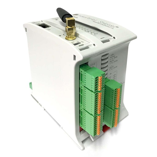
Tracker rowESP32 PLC 21 FLEX
An industrial controller built on the dual-core ESP32, for DIN rail, programmed with the Arduino IDE. The FLEX version takes one communication board: here, CAN, for the inclinometer and the drive of the row.
- Role
- Follows the sun, closes the angle loop, stows on command or on its own
- Processor
- ESP32 dual core, up to 240 MHz
- Inputs
- 13: 6 analog/digital (0-10 V, 11-bit), 7 digital optoisolated (5 to 24 Vdc), 2 of them with interrupt
- Outputs
- 8: 3 analog/digital/PWM (0-10 V, 12-bit), 5 digital optoisolated (5 to 24 Vdc)
- Option board
- CAN in this design; also 4G (M1)-NB1 IoT LTE (u-blox) or LoRa
- Wired
- Ethernet, RS-485, RS-232
- Power supply
- 12 to 24 Vdc
- Mounting
- DIN rail TS35, IP20, inside a cabinet
Outdoor row cabinets need the protection degree, the temperature range and the surge protection of the site. Check the operating range of the PLC against the climate of the plant.
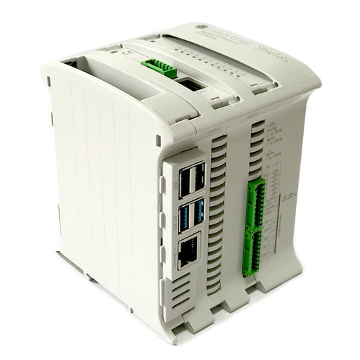
Block gatewayRASPBERRY PLC 21 FLEX
An industrial controller built on a Raspberry Pi 4 with Debian. It polls the rows and the weather station, decides the stow for the block, keeps a local buffer and serves the plant SCADA and the O&M server.
- Role
- Block gateway: polling, stow, buffer, Modbus TCP server, MQTT client
- Inputs
- 13: 6 analog/digital (0-10 V, 12-bit), 7 digital optoisolated (5-24 Vdc), 2 with interrupt
- Outputs
- 8: 3 analog/digital/PWM (0-10 V, 12-bit), 5 digital optoisolated (5-24 Vdc)
- Expansion
- One board: CAN for a CAN field bus (also LoRa, 4G or M-Bus master)
- Comms
- Ethernet 1 Gigabit + 1 10/100, 2 x RS-485, Wi-Fi, Bluetooth LE
- Computer
- Raspberry Pi 4, Debian 64-bit
- Reliability
- UPS with supercapacitors, real-time clock with battery
- Power supply
- 12 to 24 Vdc
- Mounting
- DIN rail TS35, IP20
The two RS-485 ports can serve two segments of rows, or the rows and the weather station. Size each segment by the number of rows and the poll time you need.
Questions about this case
How do you get solar tracker data into a plant SCADA?
Put a gateway in each block. It polls the tracker controllers of its rows over the field bus, adds the weather station, and serves one fixed register map over Modbus TCP to the SCADA. For history and remote work it also publishes over MQTT. See a Modbus TCP register map for a plant and a central MQTT broker for a tracker fleet.
Who decides the wind stow: the SCADA, the gateway or the tracker?
In this design, the block gateway decides from the weather station, because it is close to the field and does not depend on the plant network. Each row also goes to its safe angle by itself if it loses the gateway. The wind limits, the stow angle and the release time come from the tracker maker.
How does a tracker controller know its real angle?
With an inclinometer on the torque tube, read over CANopen in this design. The controller compares it with the target angle from the position of the sun and drives the motor until the error is small. See reading a CANopen inclinometer on a Raspberry PLC and the sun position with PyEphem.
What happens to the data when the plant network drops?
The rows keep tracking and the block keeps its stow logic. The gateway stores the records on its disk and sends them in order when the link is back, so the history has no gaps. A typical way is described in MQTT datalogging with an offline buffer.
Is this the same as the autonomous solar panels case?
No. The autonomous solar panels case is about the sun tracking of two-axis panels in groups, linked by LoRa to a master PLC with batteries. This page is about the data path of a tracker plant: rows, block gateways and the plant SCADA.
Can I try a tracker plant before I design one?
Yes. The two-axis solar tracker project pack has the code for the sun position, a CANopen drive and inclinometers, and the solar field simulator shows a day of a tracker plant with wind, faults and alarms.
Download the case study
4-page PDF with the challenge, the logic, the architecture and the hardware. No form required.
Similar project?
Tell us about your tracker plant. An engineer will answer.
Tell us the tracker type, how many rows per block, the field bus you use and what the SCADA expects. We will tell you which controllers, which bus and which data map fit.
- You get an answer from our technical team
- Row controllers, block gateways and SCADA maps
- Arduino, ESP32 or Raspberry Pi based PLCs