Case study · Public street lighting
Street lighting you can see from the office. One controller in each cabinet.
Switching, three-phase metering and alarms, from cabinet to web over GPRS.
Switch on time, measure the energy, warn on every fault.
The controller in the cabinet switches, measures and reports.
The Smart Light Controller (SLC19R) is a controller that Industrial Shields designs and builds in Sant Fruitós de Bages, close to Barcelona, for public lighting cabinets. Since 2022, city councils and provincial governments in Spain use it to manage their street lighting. Today it runs more than 300,000 luminaires. This page explains the pattern: what the controller does in one cabinet, how it talks to the platform, and which hardware you can use for a similar project.
The cabinet
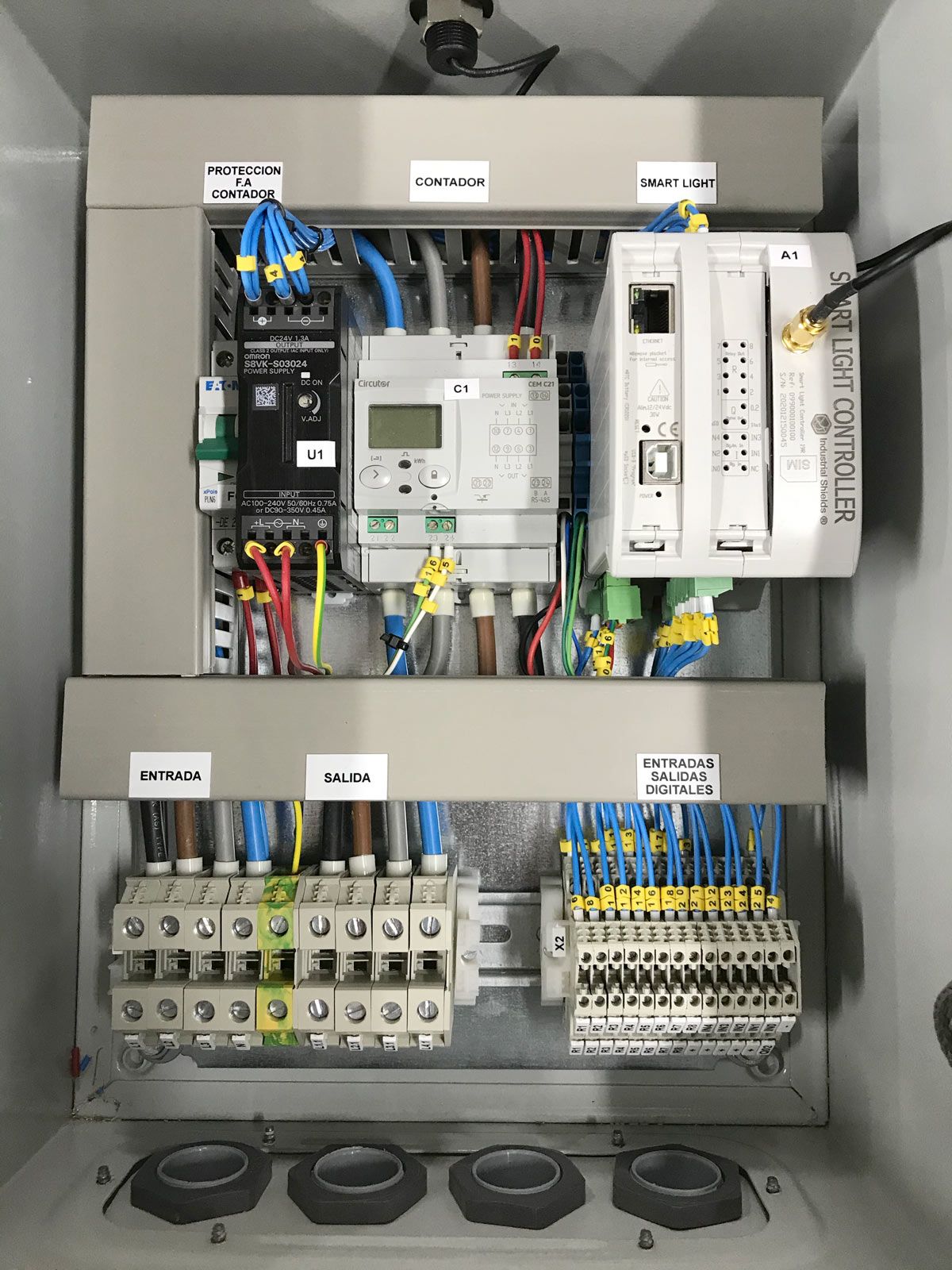
One cabinet, three parts, ready to wire.
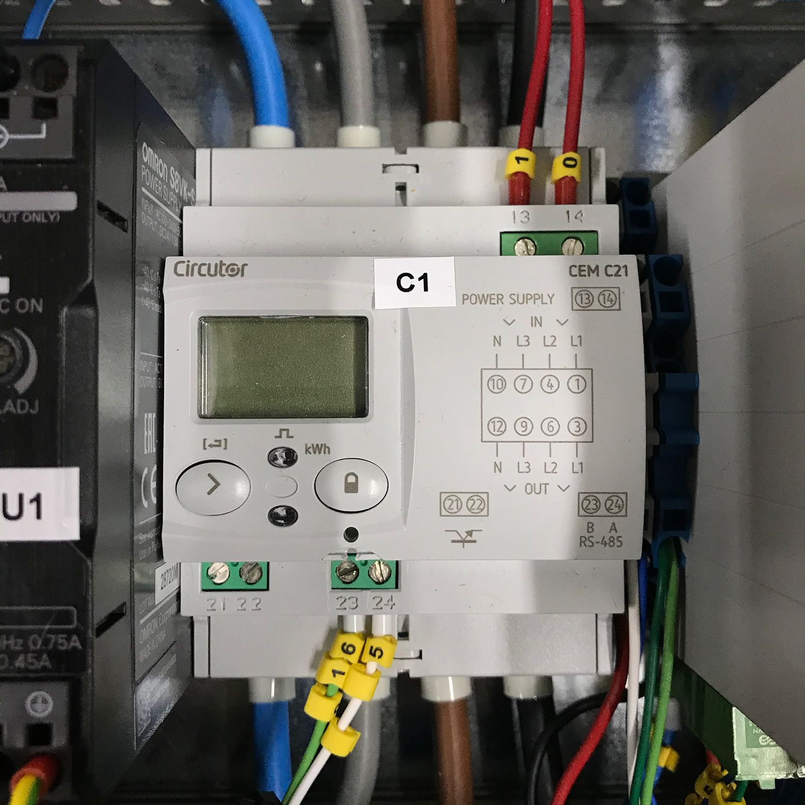
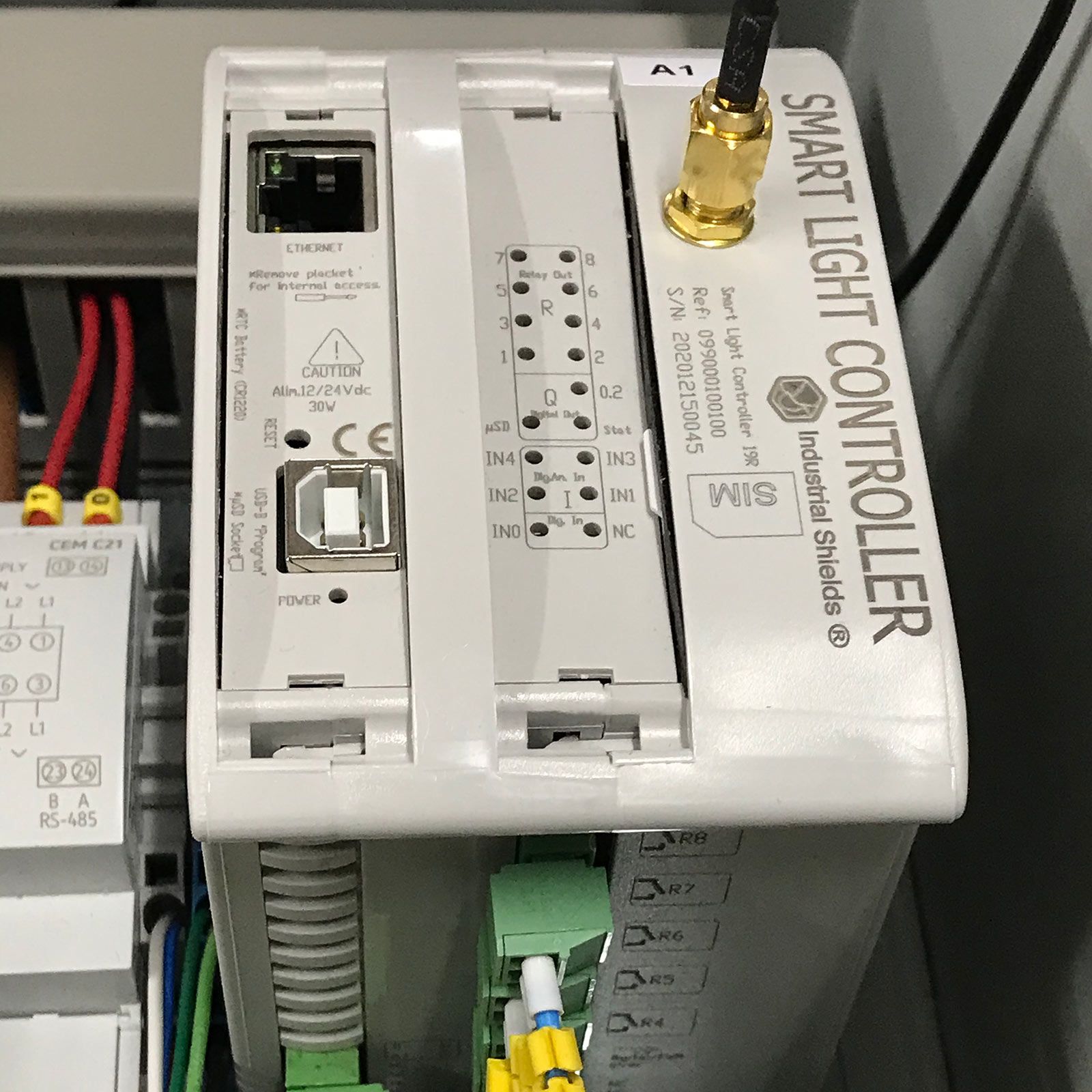
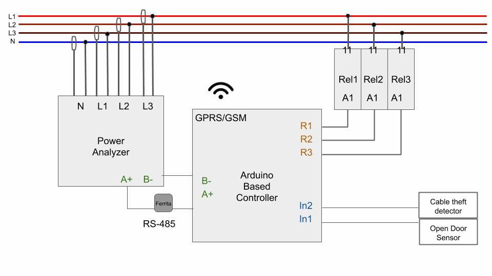
Photos from the product documentation: a reference lighting cabinet with the Smart Light Controller, the network analyzer and the power supply, and the wiring diagram of the original case.
The challenge
Light when it is needed. Know when it fails.
The lights must switch on and off at accurate times for the location and the calendar. The council needs the consumption of each cabinet, and an alarm when a lamp group fails, a door opens or a cable is cut. Each lighting cabinet needed a controller that does four jobs and reports to one platform.
Switch at the right time
On and off follow the sunset and sunrise of the town, with an offset in minutes if the council wants one.
See the faults
A failed lamp group or a tripped protection must raise an alarm on the platform.
Protect the cabinet
Open doors and cable theft are real risks for an outdoor cabinet. Both must raise an alarm.
Measure the real consumption
Voltage, current, power and power factor per phase. Real data per cabinet is the base for an energy audit.
One cabinet or a whole province
Each cabinet talks straight to the platform over the mobile network, with its own SIM. There are no concentrators and no private radio network to build.
How it works
Three loops: switch, measure, keep going.
The controller runs three loops in each cabinet: switch the circuits on an astronomical schedule, measure the three phases and raise alarms, and keep working when the link drops. The functions come from the product documentation. The values and the timing in the panels are an illustrative simulation.
On at sunset, off at sunrise, dim at night
The controller runs the on and off schedule by itself. The schedule can use fixed times or, as usual in street lighting, the sunrise and sunset times of the town, moved earlier or later by a number of minutes. A schedule can apply between two dates or stay permanent. Where the luminaires allow it, the platform also sends dimming profiles and a midnight point.
- Relay outputs drive the contactors of each circuit
- Astronomical schedule with an offset in minutes
- Dimming over U6Me2 (Tridonic) or CodedMains (Philips), where the installation allows it
- Remote on and off of one circuit or the whole cabinet
Example sunrise and sunset times. In the real system the controller stores the sunrise and sunset times of the town. Illustrative simulation. Example values and scaled times. No program or data from a real installation.
Three phases measured, every alarm on the map
A Circutor CEM-C21 network analyzer in the cabinet measures voltage, current, active power and power factor. The controller reads it over Modbus RS-485 and sends the values over GPRS. Digital inputs watch the cabinet: an open door, cable theft, a phase failure or a tripped protection. Each input is declared in the platform with its own description and its alarm state.
- Voltage, current, active power and power factor per phase
- Alarm on a sudden change in consumption
- Door and cable theft inputs, NO or NC wiring
- History with minimum, mean and maximum per phase and per day
Messages to the platform (example)
Example values and threshold. The real alarm thresholds are set per installation and are not published.
The link drops. The street stays lit.
Each cabinet works on its own. If the mobile link drops, the controller keeps its schedule and keeps switching the lights. It also keeps records on a microSD card. The platform marks a cabinet as not reachable when it gets no data from it for 60 minutes.
- Schedule stored in the controller, time from its real time clock
- Local records on a microSD card
- Not reachable after 60 minutes without data
- Remote software updates, no trip to the cabinet
Illustrative simulation. Example values and scaled times. No program or data from a real installation.
System architecture
How does one controller manage a street lighting cabinet?
The network analyzer measures the three phases and talks to the Smart Light Controller over Modbus RS-485. The controller drives the contactors with its relays and reads the alarm inputs. It sends measurements, states and alarms over GPRS/GSM to the platform, and receives on and off orders, schedules and dimming set points. The platform has a web app and a mobile app with NFC tags on the lamp posts.
| Flow | Between | Type | Purpose |
|---|---|---|---|
| Phase measurement | BetweenCEM-C21 → controller | TypeModbus RS-485 | PurposeVoltage, current, active power and power factor of the cabinet |
| Circuit switching | BetweenController → contactors | TypeRelay outputs | PurposeOn and off of each lighting circuit, or of the whole cabinet |
| Door alarm | BetweenDoor sensor → controller | TypeDigital input | PurposeDetects an open cabinet door |
| Cable theft alarm | BetweenTheft detector → controller | TypeDigital input | PurposeRaises an alarm when a cable is cut |
| Other alarms | BetweenProtection contacts → controller | TypeDigital input | PurposeFor example a phase failure or a tripped protection |
| Dimming | BetweenController → luminaire drivers | TypeU6Me2 or CodedMains | PurposeDimming profiles and midnight point, where the installation allows it |
| Data up | BetweenController → platform | TypeGPRS/GSM | PurposeMeasurements, states and alarms |
| Orders down | BetweenPlatform → controller | TypeGPRS/GSM | PurposeOn and off orders, schedules and dimming set points |
| Local records | BetweenController → microSD | TypeLocal storage | PurposeKeeps records in the cabinet |
Why it works
Why this pattern fits public lighting.
Built for the cabinet
The controller mounts on a DIN rail, runs from 12 to 24 Vdc, works from 0 to 60 °C and carries the CE marking. It acts on the contactors already in the cabinet, so it can live with the manual control.
No network to build
Each cabinet has its own SIM and talks straight to the platform. A town does not need concentrators or its own radio network.
Same tools, two generations
The first systems run on M-Duino PLCs. New deployments use the ESP32 PLC. Both are programmed with the Arduino IDE, so the code and the skills move from one to the other.
Hardware
The Smart Light Controller, and the PLCs behind it.
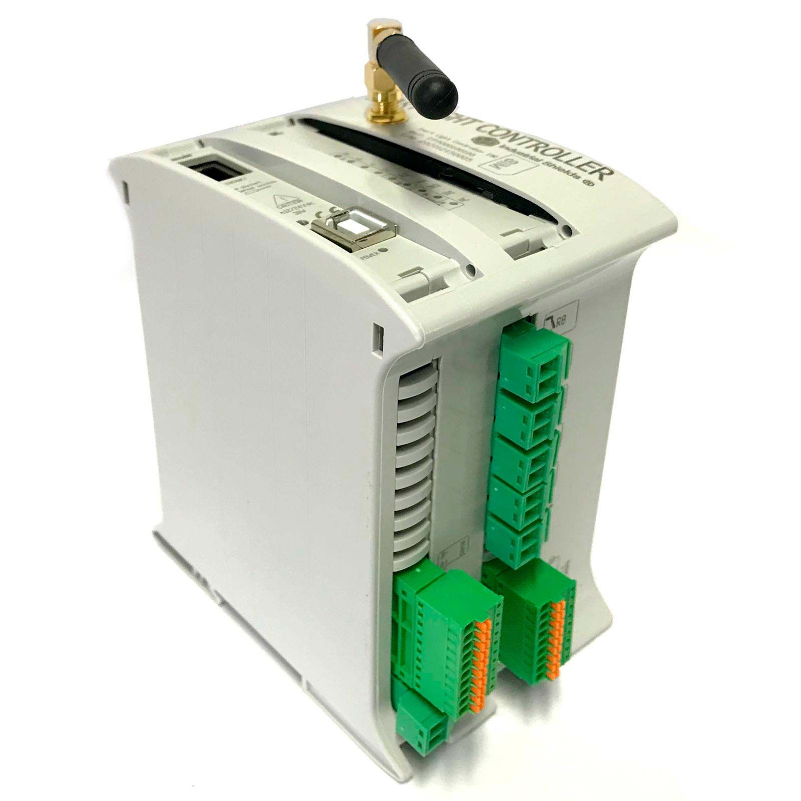
Smart Light Controller SLC19R
The controller of this case. It is supplied as a full kit, ready for the cabinet: the controller with a GPRS/GSM modem and a microSIM built in, a CEM-C21 network analyzer, a 24 Vdc 31 W power supply, the RS-485 cable and a microSD card. An outdoor kit adds the enclosure and an external antenna.
- Inputs
- 6 digital, 5 to 24 Vdc, galvanic isolation, 4 also analog 0-10 V (10-bit)
- Outputs
- 8 relays, 3 digital or analog 0-10 V (8-bit) with PWM
- Comms
- GPRS/GSM with built-in microSIM, RS-485, Ethernet, RS-232, I2C, SPI, USB
- Built in
- Real time clock, microSD slot
- Power supply
- 12 to 24 Vdc, 30 VA max
- Environment
- 0 to 60 °C, 10 to 90 % RH, DIN rail, CE marking
The Smart Light Controller is not sold in the online shop. Ask an engineer for the kit and the platform. The datasheet and the installation documents are in Spanish.
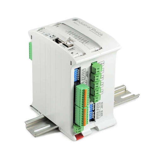
M-Duino Ethernet PLC Arduino 19R
The first Smart Light Controllers were built on M-Duino PLCs with an original Arduino Mega 2560 and the same 17 I/O layout. For your own lighting cabinet, the M-Duino 19R switches contactors with its relays and reads a network analyzer over RS-485.
- Inputs
- 6: 4 analog/digital (0-10 V, 10-bit) and 2 digital optoisolated, 5 to 24 Vdc, 2 with interrupt
- Outputs
- 11: 3 analog/digital/PWM (0-10 V, 8-bit), 8 relays (230 Vac 4 A / 24 Vdc 2 A, resistive)
- Comms
- Ethernet, RS-485, RS-232, TTL serial, I2C, SPI
- Built in
- Real time clock, microSD slot
- Power supply
- 12 to 24 Vdc
- Mounting
- DIN rail TS35, IP20
GPRS/GSM versions are described in the M-Duino GPRS family datasheet.
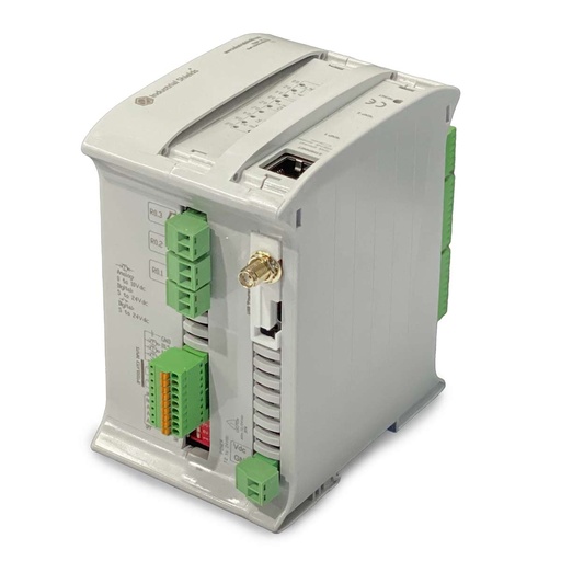
ESP32 PLC 19R
New Smart Light Controller deployments use the ESP32 PLC. One core can run the I/O and the lighting logic while the other handles communications. The ESP32 PLC 19R has the same 17 I/O layout and is programmed with the Arduino IDE.
- Processor
- ESP32 dual core, up to 240 MHz
- Inputs
- 6: 4 analog/digital (0-10 V, 11-bit) and 2 digital optoisolated, 5 to 24 Vdc
- Outputs
- 11: 3 analog/digital/PWM (0-10 V, 12-bit), 8 relays (230 Vac 4 A / 24 Vdc 2 A, resistive)
- Comms
- Ethernet, Wi-Fi, Bluetooth LE, RS-485, RS-232, I2C, SPI
- Options
- One communication board: 4G LTE-M/NB-IoT, LoRa or CAN
- Power supply
- 12 to 24 Vdc, DIN rail TS35, IP20
The ESP32 PLC 19R has the same 17 I/O layout as the first controllers, so it is the natural starting point for a similar cabinet.
Questions about this case
What does the Smart Light Controller do in a lighting cabinet?
It does three jobs at the same time. It switches the lighting circuits through the cabinet contactors, on a schedule based on sunrise and sunset. It measures the electrical values of the cabinet through a network analyzer. And it watches the cabinet with alarm inputs, such as an open door or cable theft. It sends everything to a web and mobile platform over GPRS/GSM.
How does it measure the energy consumption?
A Circutor CEM-C21 network analyzer in the cabinet measures voltage, current, active power and power factor. The controller reads it over Modbus RS-485. The platform keeps the history, with minimum, mean and maximum values per phase and per day. Together with the data of each street (type of road and lighting class), the platform calculates the energy rating under the Spanish regulation on energy efficiency in outdoor lighting (RD 1890/2008, ITC EA-01 to EA-07) and the IDAE audit protocol of October 2018. The measured consumption per cabinet is the base for an energy audit.
What happens if the GPRS link drops?
The cabinet keeps working. The controller keeps its schedule and keeps switching the lights, and it stores records on a microSD card. The platform marks the cabinet as not reachable when it gets no data for 60 minutes.
Does it work with DALI?
The product pages name DALI and 12-24 V control for drivers, power supplies and dimmable ballasts. The technical report names the dimming protocols that the platform supports: Tridonic (U6Me2) and Philips CodedMains. For a DALI bus in your own project, Industrial Shields also makes DALI versions of its M-Duino PLCs.
Is "PLC" here power line communication?
No. Here PLC means programmable logic controller. In street lighting, PLC can also mean power line communication, with concentrators and mesh nodes at lamp level. The Smart Light Controller works at cabinet level and reaches the platform over GPRS/GSM, with no concentrators.
Can I build a similar system with a standard PLC?
Yes, as a pattern. An M-Duino 19R or an ESP32 PLC 19R has 8 relays for the contactors, digital inputs for the alarms and RS-485 for a Modbus network analyzer. Add a cellular link and a server or SCADA for the data. The PLC Solution Library has a Modbus RTU master example over RS-485 to start from.
Download the case study
4-page PDF with the challenge, the logic, the architecture and the hardware. No form required.
Lighting project?
Tell us about your cabinets. An engineer will answer.
Tell us how many lighting cabinets you manage, how many circuits each one has, and how the luminaires dim. We will tell you if the Smart Light Controller fits, or which PLC to use for your own system.
- You get an answer from our technical team
- Smart Light Controller kit and platform, or your own design
- Arduino, ESP32 or Raspberry Pi based PLCs