Case study · Smart hotel · Raspberry PLC 19R
Check in at reception. The room gets ready.
One ID scan at the entrance. A PLC and a panel in every room.
Guests want the room their way. Staff want less paperwork. Owners want lower energy bills.
So the ID is scanned once, and each room starts only when a guest gets it.
This case describes a model that Industrial Shields designed in 2020 to turn a hotel into a smart hotel. It does not name a hotel or a customer, and it does not publish results. The original names a TinkerTouch S 10.1" panel and Raspberry based PLCs; this page uses the current products. The preferences, rooms, set values, times and levels in the panels are examples.
The challenge
Connect the reception, every room and the cloud.
A smart hotel is a hotel where the devices are connected to each other and to the cloud. Guests control many devices from one point, and the system answers their preferences. The goal of the model is a viable way to do it: PLCs, panels, sensors, an ID scanner and a server for all the information.
Check-in at one point
A panel at the entrance welcomes the guest. It scans the ID, fills the forms, asks for the signature and sends a copy to the guest by email.
A room on preferences
On the same panel, the guest chooses preferences. The room is assigned from them, and the data and the room number go to the room before the guest does.
A room that starts with the guest
The fridge switches on when the room is assigned, not before. The air conditioning stops at the set temperature. The LED lights change intensity.
Information at hand
The room panel shows the clock, the hours to checkout, the next alarm, the best time for the spa or the gym, city maps, restaurant times and menus, and the hotel contacts.
One master, many rooms
The PLC at the entrance is the master of a Wi-Fi network. A PLC and a panel in each room are its slaves. The master sends the guest data to the cloud over mobile data (GPRS in the 2020 case).
How it works
Three loops: check-in, room, bath.
Each panel shows one part of the model. Press the buttons and move the controls. The panels are illustrative simulations: the rooms, preferences, set values and levels are examples, not data from a hotel.
Scan the ID once. Assign the room from the preferences.
At the entrance, the master panel welcomes the guest. The scanner reads the ID card over RS-485, the panel fills the forms, asks for the signature and emails a copy. The guest chooses preferences and the room is assigned from them. Then the main PLC tells the room over Wi-Fi and sends the data to the cloud. Pick preferences, scan, then sign.
- ID scanner on RS-485
- Forms, signature and email from one scan
- Room number to the room PLC over Wi-Fi
Check-in log (example)
Illustrative simulation. Example values, not data from a hotel. Example rooms and preferences. As in the case: the scanner reads the ID, the panel fills the forms, asks for the signature and emails a copy, and the room is assigned from the preferences. A typical way to do it: the free room that matches most preferences wins, and the master PLC sends the room number to the room PLC over the Wi-Fi network.
Climate, light and fridge, from the room panel.
In each room, a PLC with relay outputs switches the 230 V loads, and a panel is the point of control. A temperature sensor reads the room and the air conditioning runs on a relay. The LEDs dim with a PWM output. The fridge switches on only when the room is assigned. Change the season, move the set value, then check the guest out.
- Air conditioning on a relay, off at the set value
- LED intensity from a PWM output
- Fridge on only while the room is assigned
Room events (example)
Illustrative simulation. Example values, not data from a hotel. Example set values, faster than real time. As in the case: the air conditioning is on a relay and stops once the room reaches the set temperature, the LED intensity comes from a PWM output, and the fridge is on only while the room is assigned. A typical way to do it: a band of 1 °C around the set value, so the relay does not switch every second; at checkout, the room goes back to its idle state.
Fill the bath from the panel.
Two solenoid valves, one for hot water and one for cold, sit on outputs of the room PLC. The guest starts the filling from the panel and finds the bath ready. Choose the hot water share and fill the bath.
- Hot and cold solenoid valves
- Started from the room panel
- Level switch and mixing valve (typical, not in the case)
Bath log (example)
Illustrative simulation. Example values, not data from a hotel. Example level, times and temperatures. As in the case: two solenoid valves, hot and cold, fill the bath when the guest asks from the panel. A typical way to do it: the PLC opens the hot and the cold valve in turns, in the share the guest chose; a level switch stops the filling; and a thermostatic mixing valve on the hot line limits the hottest water, whatever the program does.
System architecture
How do you build a smart hotel with PLCs?
At the entrance, the ID scanner reaches the reception panel over RS-485, and the panel talks to the main PLC over Ethernet. The main PLC is the master of a Wi-Fi network to the rooms and sends the data to the cloud over mobile data. In each room, a panel talks to a Raspberry PLC 19R over Ethernet, and the PLC switches the air conditioning, the LED driver, the fridge and the two bath valves. The scheme of the case shows the same links.
| Signal | Between | Type | Purpose |
|---|---|---|---|
| ID data | BetweenID scanner → reception panel | TypeRS-485 | PurposeFills the forms and the guest record |
| Check-in and room | BetweenReception panel ↔ main PLC | TypeEthernet | PurposePreferences, signature, room assigned |
| Room commands | BetweenMain PLC ↔ room PLC | TypeWi-Fi | PurposeRoom number, guest name, check-in and checkout |
| Guest data | BetweenMain PLC → cloud server | TypeMobile data (4G today, GPRS in the case) | PurposeStores the check-in data |
| Room temperature | BetweenTemperature sensor → room PLC | TypeDigital in (as in the case) or 0-10 V analog in | PurposeCompared with the set value of the guest |
| Bath level | BetweenLevel switch → room PLC | TypeDigital in | PurposeStops the filling (example) |
| Air conditioning | BetweenRoom PLC → air conditioning | TypeRelay out | PurposeOn away from the set value, off at it |
| LED lights | BetweenRoom PLC → LED driver | TypePWM / 0-10 V out | PurposeLight intensity |
| Fridge | BetweenRoom PLC → fridge | TypeRelay out | PurposeOn only while the room is assigned |
| Hot water | BetweenRoom PLC → solenoid valve | TypeRelay out (digital outputs in the case) | PurposeFills the bath |
| Cold water | BetweenRoom PLC → solenoid valve | TypeRelay out (digital outputs in the case) | PurposeFills the bath |
| Room menu | BetweenRoom PLC ↔ room panel | TypeEthernet | PurposeSet values, light, bath, guest information |
Why this design
Data entered once. Rooms that start with the guest.
One scan, many uses
The ID is read once at the entrance. The same data fills the forms, goes into the email to the guest, picks the room and reaches the room panel, which greets the guest by name.
Rooms start with the guest
The fridge works only while the room is assigned, and the air conditioning stops at the set temperature. The case expects lower energy bills from this.
One master, many rooms
Every room has the same PLC, the same panel and the same program. A new room is one more slave on the Wi-Fi network of the master PLC.
Relays for 230 V loads
The Raspberry PLC 19R has 8 relays, up to 4 A at 230 Vac or 2 A at 24 Vdc with a resistive load. For the air conditioning compressor and the valve coils, a relay drives a contactor or an interface relay, with an RC snubber.
A control network for the hotel
A typical way to do it: the room PLCs use their own Wi-Fi network, separate from the guest Wi-Fi, so a guest cannot reach a room controller. In a real building, the network runs on the hotel access points; the main PLC is the master of the data, not the radio.
Room for maintenance data
The model does not implement preemptive maintenance. The case says how to add it: sensors for pressure, temperature, humidity or air quality on the devices, with the data sent to the server for analysis.
Hardware
One PLC model for the entrance and the rooms.

RASPBERRY PLC 19R
An industrial PLC built around a Raspberry Pi 4, with 6 inputs and 11 outputs, 8 of them relays, two Ethernet ports, two RS-485 ports, Wi-Fi and Bluetooth LE. In each room it switches the loads; at the entrance it is the master of the Wi-Fi network.
- Role
- Main PLC at the entrance; room PLC in each room
- Inputs
- 6: 4 analog/digital (0-10 V, 12-bit), 2 digital optoisolated (5 to 24 Vdc)
- Outputs
- 11: 8 relays, 3 analog/digital/PWM (0-10 V, 12-bit)
- Relays
- Up to 4 A at 230 Vac or 2 A at 24 Vdc, resistive load
- Comms
- 1 x Gigabit and 1 x 10/100 Ethernet, 2 x RS-485, Wi-Fi, Bluetooth LE
- Expansion
- One optional board: 4G (LTE-M/NB-IoT or LTE Cat 4), LoRa or CAN
- Software
- Debian 64-bit; Python, Node-RED, C/C++
- Power and mounting
- 12 to 24 Vdc, UPS for safe shutdown, DIN rail TS35, IP20, inside a cabinet
The slides of the case name Raspberry based PLCs and the scheme labels the room PLC "Raspberry Relay PLC"; the web version says Arduino PLC. No source fixes the model. This page uses the Raspberry PLC 19R: its relays switch the 230 V loads, an analog/PWM output drives the LED driver and Wi-Fi is built in. For the main PLC, the 4G board replaces the GPRS link of the 2020 case, as many operators have switched 2G off or plan to. See the product page for the family datasheet.
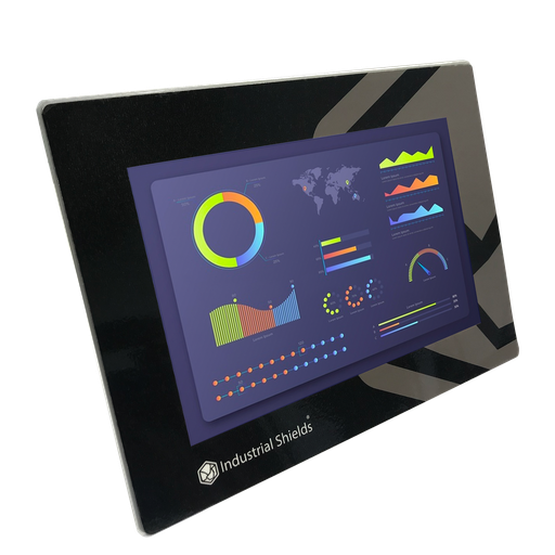
TouchBerry Pi Panel PC 10.1" CORE
The point of control: a Raspberry Pi 4 behind a 10.1" capacitive touchscreen, on Ethernet to the PLC. At the entrance it runs the check-in; in the room it shows the menu for the climate, the light, the bath and the guest information.
- Role
- Check-in at the entrance; room menu in each room
- Screen
- 10.1" IPS, 1280 x 800, capacitive, 900 nits
- Software
- Linux preinstalled; HMI in Node-RED, Python or a browser
- Comms
- Gigabit Ethernet, 4 x USB, one serial port (RS-485, RS-232 or TTL, chosen at order)
- Power
- 12 to 24 Vdc, UPS for safe shutdown
- Environment
- 0 to 45 °C, 10 to 90 % RH without condensation, IP20 front
The original case names the TinkerTouch S 10.1", which is no longer sold, and the web version links to the TouchBerry 10.1". Today it is the TouchBerry Pi Panel PC 10.1" CORE. In the scheme of the case, the ID scanner connects to the reception panel over RS-485: order that panel with its serial port as RS-485. For a full-screen guest menu, see kiosk mode for a Node-RED dashboard. The FLEX version adds options such as an IP65 front.
Questions about this case
What is a smart hotel?
A hotel where the devices are connected to each other and to the cloud, so they can work together and give useful information. Guests control many devices from one point, such as a room panel, and the system answers their preferences. In this model, a PLC and a panel in each room do that job, and a master at the entrance connects them.
How does check-in with an ID scanner work in this design?
The scanner reads the ID card and sends the data over RS-485 to the reception panel. The panel fills the forms, asks for the signature and emails a copy to the guest. The guest chooses preferences, the room is assigned from them, and the main PLC sends the room number and the guest data to the room over Wi-Fi.
How do the room PLCs talk to the reception?
Over Wi-Fi, with the PLC at the entrance as the master and the room PLCs as slaves, as in the case. The case does not name the protocol. A typical way to do it is MQTT, with the broker on the main PLC, on a Wi-Fi network for the controllers only, separate from the guest Wi-Fi. See a central Mosquitto MQTT broker (the example is a solar tracker; the pattern is the same).
Which loads does each room PLC switch?
The air conditioning and the fridge on relays, the two bath valves (hot and cold) on outputs, and the LED lights on a PWM output. A temperature sensor reads the room. On a Raspberry PLC 19R, that is 4 of the 8 relays and 1 of the 3 analog/PWM outputs, so there is room for more loads. The case puts the valves on digital outputs; on a Raspberry PLC 19R they go on relays.
Can a hotel PLC still use GPRS?
GPRS runs on 2G networks, and many operators have switched 2G off or plan to. The 2020 case sends the data to the cloud over GPRS. Today, the Raspberry PLC 19R takes an optional 4G board (LTE-M/NB-IoT or LTE Cat 4) for the same job. If the hotel has a wired internet line, Ethernet also works.
What about the privacy of guest data?
The case warns about it: a smart hotel must be transparent and comply with data protection law. In the EU, guest ID data is personal data under the GDPR (Regulation (EU) 2016/679). A typical way to do it: keep only the data you need, store it on a server the hotel controls, in the cloud or on site, and use only grouped data, such as the most used services and hours, to set the default options. Check the guest registration rules of your country too.
Automating a hotel?
Tell us about your hotel. An engineer will answer.
Tell us how many rooms you have, how check-in works today, which loads each room has and how the building is connected. We will propose the controllers, the panels and the network.
- You get an answer from our technical team
- Check-in, room control and network for your hotel
- Raspberry Pi, ESP32 or Arduino based PLCs