Case study · Public spaces · ESP32 PLC LoRa
Count the square. Plan the next event.
Photocells at the accesses, an ESP32 PLC with LoRa, and a history in the cloud.
Every pass is a pulse. Every pulse is a count.
The counts travel by LoRa, and the history tells you how many people the next event will bring.
This case is a design proposal by Industrial Shields engineers. They wrote it as a simplified model, so that each customer can adapt it to its own site. It does not describe one installation, and it does not name a city or a square. The case gives the goal, the sensors, the PLC and the path of the data. Intervals, counts, payloads, network details and event data on this page are examples of a typical way to do it.
The challenge
Know how many people come, before the next event.
The people who manage a big square want to know in advance how many people will come to a public event or a demonstration. Then they can decide, for example, how many police officers or ambulances they need. The way to anticipate is to analyse the data of the past events.
Count at every access
Several photoelectric sensors at the accesses of the square detect each person who passes. Each pulse adds one to a counter in the PLC.
Keep the data safe
The counters are the registers of the system. The PLC sends them on a fixed cycle, so that the data is stored safely in a general register.
No data cable to the office
The PLC sends the counters by LoRa radio to the cloud, so the square needs no network cable or Wi-Fi.
From counts to plans
The history shows trends and preferences, such as which events are the most crowded. Per access, it also shows where people come in.
A simple signal, a lot of data
A pulse per person is a small signal. Months of pulses per access and per hour become the patterns that a planning model needs.
How it works
Three stages: count, send, plan.
Each stage shows one part of the path of the data. Press the buttons. The panels are illustrative simulations: counts, intervals, payloads and event data are examples, not data from a real square.
A beam breaks. The counter of its access adds one.
Each access has a photoelectric sensor with its reflector. When a person crosses the beam, the sensor gives a high voltage level to a digital input of the PLC. The PLC sees the pulse and adds one to the counter of that access. Send people through the accesses, then try two people side by side.
- One photocell per access on a digital input
- One counter per access in the PLC
- Counts on the edge of the pulse
PLC events (example)
- Press a button to send a person through an access.
Illustrative simulation. Example values, no data from a real square. One beam counts passes, not the direction, and two people side by side give one pulse. The case does not publish how it counts exits or its accuracy. A typical way to see the direction: two beams a short distance apart, and the order in which they break.
The totals go to the cloud by LoRa, on a fixed cycle.
The PLC packs the counters into a small frame and sends it on a fixed period. A typical way to reach the cloud is LoRaWAN: a gateway receives the frame and a network server passes it on. Send totals, not increments: if a frame is lost, the next one carries the full count. Change the interval and the spreading factor, then lose a frame.
- Totals in a few bytes
- Airtime grows with the spreading factor
- A lost frame does not lose people
Frames to the cloud (example)
Illustrative simulation. Example values, no data from a real square. Example payload: one 32-bit total per access, 12 bytes, plus 13 bytes of LoRaWAN overhead, at 125 kHz and coding rate 4/5. The case says LoRa to the cloud and does not name the network or the interval. The Things Network fair use policy gives each node 30 s of uplink airtime per 24 hours. Time runs fast: one second is one period.
Past events of the same type give the next forecast.
In the cloud, every frame adds a point to the history of each access. Grouped by hour and by event type, the history shows the pattern of each kind of event: when people arrive, how many, and through which access. Pick an event type.
- History per access, per hour and per event
- Forecast from similar past events
- Numbers for the people who plan the resources
Planning input (example)
Illustrative simulation. Example values, no data from a real square. Example data from four past events of each type, not from a real square. A typical way: average the past events of the same type, and use the spread between them as the uncertainty. The planner turns these numbers into police, ambulance and steward needs with its own rules.
System architecture
How does a PLC count people in a public square?
Photoelectric sensors at the accesses of the square give a pulse to the digital inputs of an ESP32 PLC 21 FLEX with a LoRa board. The PLC keeps one counter per access and sends the counters by LoRa on a fixed cycle. A typical way to reach the cloud: a LoRaWAN gateway and a network server, which pass the decoded counts to a database. There the counts become a history for trends and forecasts.
| Signal | Between | Type | Purpose |
|---|---|---|---|
| Pass at access A, B, C | BetweenPhotocells (×3) → ESP32 PLC 21 | TypeDigital in | PurposeA high level on each beam break: one pulse |
| Counter of each access | BetweenInside the PLC | TypeRegister | PurposeAdds one on each pulse. The case calls it the register |
| Saved totals (typical way) | BetweenESP32 PLC 21 → NVS memory | TypeMemory | PurposeTotals that survive a restart or a power cut |
| Counts frame | BetweenESP32 PLC 21 → gateway | TypeLoRa | PurposeTotals of all the accesses, on a fixed cycle |
| Decoded counts | BetweenNetwork server → cloud | TypeMQTT or webhook | PurposeThe general register of the case (typical way) |
| History and forecast | BetweenCloud → planning team | TypeDashboard | PurposeTrends per access, hour and event type |
Why it works
A small signal, sent with care.
A pulse is enough
The photocell gives a high level when a person crosses the beam. The PLC turns each pulse into one count. No camera and no image processing.
Totals, not increments
Each frame carries the full count of each access. If a frame is lost, the next one corrects the cloud, and no person is lost.
Radio where there is no cable
LoRa carries the counters from the PLC to a gateway, with no network cable from the square and no SIM card in the PLC.
Few bytes for a shared band
Three 32-bit totals fit in 12 bytes. Short frames keep the airtime inside the duty cycle and the network limits.
History first
The case starts from the data of past events. A forecast is only as good as the history behind it, so the counting starts long before the event.
A simple base to grow
The case is a simplified model. More accesses or a second beam for the direction are changes in the same Arduino IDE program.
Hardware
One ESP32 PLC with LoRa for the accesses of the square.
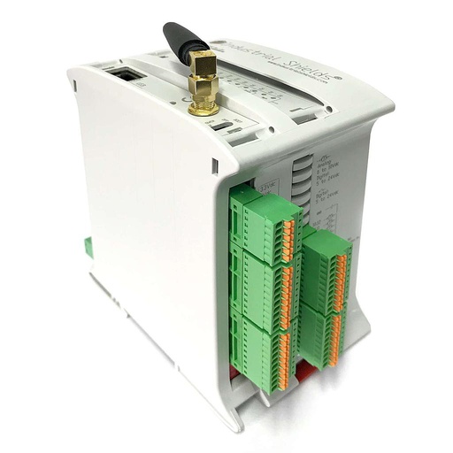
ESP32 PLC 21 FLEX
An industrial controller built on the dual-core ESP32, for DIN rail, programmed with the Arduino IDE. The FLEX version takes one communication board: here, LoRa for the EU868 band, with a module that has the LoRaWAN stack inside. In this case it reads the photocells, keeps the counters and sends them to the cloud by LoRa.
- Role
- Count the passes at each access, send the totals by LoRa
- Processor
- ESP32 dual core, up to 240 MHz
- Inputs
- 13: 6 analog/digital (0-10 V, 11-bit), 7 digital optoisolated (5 to 24 Vdc), 2 of them with interrupt
- Outputs
- 8: 3 analog/digital/PWM (0-10 V, 12-bit), 5 digital optoisolated (5 to 24 Vdc)
- Option board
- One: LoRa (EU868, US902 or Asia band), 4G LTE-M/NB-IoT or CAN
- Communications
- Ethernet, Wi-Fi, Bluetooth LE, RS-485, RS-232
- Clock
- DS3231 real-time clock with backup battery
- Programming
- Arduino IDE
- Power supply
- 12 to 24 Vdc
- Mounting
- DIN rail TS35, IP20, inside a cabinet
The original case used an M-Duino 21 with LoRa (the "M-Duino PLC Arduino Ethernet & LoRa 21 I/Os Analog/Digital PLUS"). Today, the equivalent that you can buy with LoRa is the ESP32 PLC 21 FLEX with the LoRa (Europe - EU868) board, or the US902 board in America. It has the same count of inputs and outputs, and it is also programmed with the Arduino IDE. According to the family datasheet, the LoRa board uses a Microchip RN2483 module (RN2903 for US902) with the LoRaWAN stack inside: the program sends commands such as join and send over UART. Three accesses with one beam each use 3 of the 7 isolated digital inputs; with two beams per access, three accesses use 6. A typical way to wire the photocells: 24 Vdc sensors with a PNP output on the isolated inputs. The PLC goes in a cabinet (IP20, no condensation); outdoors, choose a cabinet for the local climate and photocells rated for outdoor use. If the accesses are far apart, a typical way is one PLC per access group, each with its own LoRa board.
Questions about this case
How do you count people at the entrances of a public square?
Put a photoelectric sensor at each access and wire it to a digital input of a PLC. Each time a person crosses the beam, the sensor gives a pulse and the PLC adds one to the counter of that access. On this page, an ESP32 PLC 21 FLEX with a LoRa board keeps the counters and sends them to the cloud on a fixed cycle, where they become a history per access and per hour.
Can a photocell tell entries from exits?
Not with one beam. One beam counts passes in both directions, and two people side by side give one pulse. A typical way to get the direction: two beams a short distance apart, so the order in which they break tells entry or exit; or separate lanes to enter and to leave. The case does not publish how it counts exits or its accuracy.
How often should a PLC send counts over LoRaWAN?
As often as the airtime allows. In the EU863-870 band, the LoRaWAN sub-bands have a 1 % duty cycle, and The Things Network fair use policy gives each node 30 s of uplink airtime per 24 hours. Three 32-bit totals are 12 bytes; with 13 bytes of LoRaWAN overhead, a frame takes 61.7 ms at SF7 and 411.6 ms at SF10. One frame every 15 minutes uses about 6 s a day at SF7 and about 40 s a day at SF10. That is above the 30 s fair use budget: at SF10, send one frame every 20 minutes or less often (72 frames a day). See LoRaWAN with a PLC: OTAA, ABP and The Things Network.
What happens to the counts if a LoRa frame is lost?
Nothing is lost if the PLC sends totals and not increments. The next frame carries the full count of each access, and the cloud computes the people per period from the difference. The LoRaWAN frame counter shows how many frames are missing. A typical way to keep the totals through a restart or a power cut: store them in the non-volatile memory of the PLC. See persistent counters on an ESP32 PLC and LoRaWAN payload bit packing.
Does counting with photocells collect personal data?
A photocell gives no image and no identity. It only tells the PLC that the beam was broken. The system stores totals per access and per period. Check the rules of your country for the platform that keeps the data and for any other sensor you add.
How do past counts help to plan an event?
The case starts from the data of past events. Grouped by event type, access and hour, the counts show when people arrive, how many come and which accesses they use. A typical way to forecast: the average of past events of the same type, with their spread as the uncertainty. With that number, the planners decide, for example, how many police officers or ambulances the event needs.
Download the case study
4-page PDF with the challenge, the logic, the architecture and the hardware. No form required.
Similar project?
Tell us your accesses and your data. An engineer will answer.
Tell us how many accesses you want to count, how far apart they are, which network reaches the site, and where the data must go. We will tell you which controller and which radio fit, and how to wire the sensors.
- You get an answer from our technical team
- I/O count and radio choice: LoRa, LoRaWAN or 4G
- Arduino, ESP32 or Raspberry Pi based PLCs