Case study · Water network · LoRaWAN
Many sites. One control room.
Linux PLCs at the plant, ESP32 PLCs in the field, LoRaWAN between them.
The pumps follow the level. The radio only reports.
A silent site is an alarm too.
This case describes a telecontrol pattern for a municipal water network: a wastewater treatment plant, the pumping stations around it, and small remote points such as tanks and wells. It is based on the equipment of a real project for a water operator. We do not name the operator, its sites or the number of sites. Levels, periods, ranges and coverage on this page are examples: a typical way to do it. For chemical dosing in one station, see the water treatment case.
The challenge
Many sites, few people, long distances.
A municipal water network is spread out. The treatment plant, the pumping stations, the tanks and the wells are often kilometres apart, and many have no fixed network line. The operator must see every site, get the alarm when a pump fails, and act before a wet well overflows. The control room must also know when a site stops talking.
Local control first
A pumping station starts and stops its pumps on its own level. The radio link must never be part of that loop.
Small data, long range
A remote point sends a few values: a level, the pump states, an alarm. LoRaWAN carries that far, with no SIM card per site.
Many signals at the plant
The treatment plant has 4-20 mA transmitters and devices that already speak Modbus. One controller must read both.
Silence is a state
If a site stops reporting, the control room must show it. No news must not look like good news.
One view for the operator
A panel at each site cabinet, a large screen in the control room, and the alarm on the phone of the person on call. The same data, with the same timestamp, whatever the path it took.
How it works
Three stages: the station, the radio, the plant.
Each stage shows one part of the network. Press the buttons and move the sliders. The panels are illustrative simulations: levels, periods, ranges and timings are examples, not data from the operator.
The level starts the pumps. The radio sends the news.
An ESP32 PLC 21 reads the wet well level from a 4-20 mA transmitter. It starts the duty pump at the start level and stops the pumps at the stop level. If the level keeps rising, the second pump helps. The pumps alternate, and a pump fault moves the work to the other pump. The PLC sends a short LoRaWAN frame on a fixed period, and at once on an event: a fault or a high level. Move the inflow. Press Pump 1 fault.
- Wet well level: 4-20 mA through a 500 Ω shunt
- Duty and assist pumps with alternation
- A frame on each period, and one on each event
Station events (example)
Illustrative simulation. Example values, no data from the operator. Example levels: duty pump on at 50 %, assist pump on at 70 %, both off at 20 %, high level alarm at 90 %. Example period: one frame every 15 min, shown as every 6 s. A 4-byte frame is enough for the level, the pump states and the alarms.
Any gateway can hear a site. Silence has a timer.
A LoRaWAN device is not paired with one gateway. Every gateway in range receives its frame, and the network server removes the copies. A site covered by two gateways keeps reporting when one gateway fails. A site covered by one gateway goes silent. The control room knows the period of each site: after three missed frames, it marks the site as stale. When the link comes back, the frame counter shows how many frames were lost. Switch a gateway off.
- Each frame is heard by every gateway in range
- The network server removes the copies
- Stale after three missed periods (example)
Control room events (example)
Illustrative simulation. Example values, no data from the operator. Example: each site sends one frame every 15 min, shown as every 3 s. Station A is in range of gateway 1, the tank of gateway 2, and station B of both. Real coverage depends on distance, terrain and antennas. A typical way to recover lost data: the site keeps its readings in local storage, and the control room asks for the missing ones.
Run a full water network in the Remote Site Telemetry simulator
Milliamps, volts, units. A broken wire is not a zero.
At the plant, a Raspberry PLC 42 reads the 4-20 mA transmitters, the devices that already speak Modbus, and a local HMI panel. Its analog inputs measure 0-10 V, so each 4-20 mA loop goes through a shunt resistor. 4 mA is the zero of the scale. A reading of 3.6 mA or less is a fault, such as a broken wire or a failed transmitter, not a zero flow. The PLC sends each value to the control room over MQTT, with a quality flag. Move the current. Cut the wire. Change the shunt.
- 4-20 mA to 0-10 V with a shunt resistor
- Fault limits from NAMUR NE 43
- Each value with a quality flag over MQTT
Values sent to the control room (example)
Illustrative simulation. Example values, no data from the operator. Example transmitter: inlet flow, 0 to 300 m³/h over 4-20 mA. Fault limits from NAMUR NE 43: 3.6 mA or less, or 21 mA or more. With 500 Ω, 20 mA gives 10 V, the top of the input, so the PLC cannot see the high fault and the panel marks 20 mA and more as uncertain. With 470 Ω, 21 mA gives 9.87 V. Check the maximum input voltage in the datasheet and use a precision resistor.
System architecture
How does telecontrol of a water network fit together?
Two kinds of PLC, two paths. In the field, an ESP32 PLC 21 with a LoRa board runs each remote point: it controls the pumps on site and sends short LoRaWAN frames. Outdoor gateways receive the frames and pass them to a LoRaWAN network server, which sends the decoded data to the control room. At the treatment plant, a Raspberry PLC 42 reads the 4-20 mA transmitters, the Modbus RTU devices on RS-485 and the Modbus TCP remote I/O, shows the plant on a local HMI panel and publishes its values over MQTT. The control room puts both paths on one screen.
| Signal | Between | Type | Purpose |
|---|---|---|---|
| Wet well level | BetweenTransmitter → ESP32 PLC 21 | Type4-20 mA, 500 Ω | PurposeStarts and stops the pumps on site |
| Pump running, pump fault | BetweenContactor, thermal relay → ESP32 PLC 21 | TypeDigital in | PurposeConfirms each pump. A fault moves the work to the other pump |
| Pump command | BetweenESP32 PLC 21 → contactor | TypeDigital out | PurposeThrough an interposing relay to the contactor coil |
| Site status | BetweenESP32 PLC 21 → gateways | TypeLoRaWAN | PurposeA few bytes: level, pump states, alarms. On each period and on each event |
| Decoded frames | BetweenNetwork server → control room | TypeMQTT or HTTP | PurposeData of all the remote points, without copies |
| Plant process values | BetweenTransmitters → Raspberry PLC 42 | Type4-20 mA, shunt | PurposeFlows and levels of the plant (example) |
| Installed devices | BetweenDrives, meters → Raspberry PLC 42 | TypeModbus RTU | PurposeValues the devices already compute, on RS-485 |
| Remote I/O | BetweenI/O modules → Raspberry PLC 42 | TypeModbus TCP | PurposeMore digital signals without new cables to the cabinet |
| Local view | BetweenHMI panel ↔ Raspberry PLC 42 | TypeDisplay and touch | PurposePlant view and local commands. The case does not publish how the panel connects |
| Plant data | BetweenRaspberry PLC 42 → control room | TypeMQTT | PurposeEach value with its timestamp and quality, over Ethernet or 4G |
Why it works
Control on site. Data in one place.
Control stays on site
The pumps react to the level inside the PLC, every scan. A lost frame changes what the control room sees, not what the pump does.
Any gateway hears the node
LoRaWAN devices are not tied to one gateway. Two gateways that cover the same sites give each site a second path, and the network server keeps one copy of each frame.
Few bytes, on purpose
Short frames use less airtime. In EU868, the main channels allow 1 % of airtime per device. Pack the bits: see LoRaWAN payload bit packing.
A broken wire is not a zero
With 4 mA as the zero of the scale, a dead loop reads near 0 mA and the PLC flags it. The control room gets a bad quality flag, not a false zero flow.
Linux where the signals are
The Raspberry PLC 42 runs Debian, with two RS-485 ports, two Ethernet ports and a real-time clock. Its UPS with supercapacitors shuts Linux down cleanly on a power cut.
Silence has a timer
The control room knows the period of each site. After a set number of missed frames, the site turns stale. The frame counter tells how many frames were lost.
Hardware used
Linux at the plant. ESP32 in the field. Screens for people.
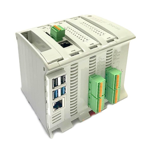
Raspberry PLC 42
An industrial PLC built around a Raspberry Pi 4, with Debian 64-bit. At the plant it reads the 4-20 mA transmitters through shunts, talks Modbus RTU on its two RS-485 ports and Modbus TCP on Ethernet, shows the plant on the local HMI panel and publishes the values over MQTT. You program it in Python, Node-RED or C/C++.
- Role
- Plant controller: analog signals, Modbus, local HMI, MQTT
- Computer
- Raspberry Pi 4, quad core 64-bit, 1.8 GHz, 2, 4 or 8 GB RAM
- Inputs
- 26: 12 analog/digital (0-10 V, 12-bit), 14 digital optoisolated (5-24 Vdc)
- Outputs
- 16: 6 analog/digital/PWM (0-10 V), 10 digital optoisolated (5-24 Vdc)
- Comms
- 2 Ethernet (Gigabit and 10/100), 2 RS-485, Wi-Fi, Bluetooth LE
- Option board
- One: LoRa (EU, US or Asia band), 4G LTE-M/NB-IoT or CAN
- Reliability
- UPS with supercapacitors for a safe shutdown, RTC with battery
- Power, mounting
- 12 to 24 Vdc, DIN rail TS35, IP20
In the project behind this case, the plant controllers are Raspberry PLC 42 units. They send their data over Ethernet, or over a 4G board where a site has no wired network.
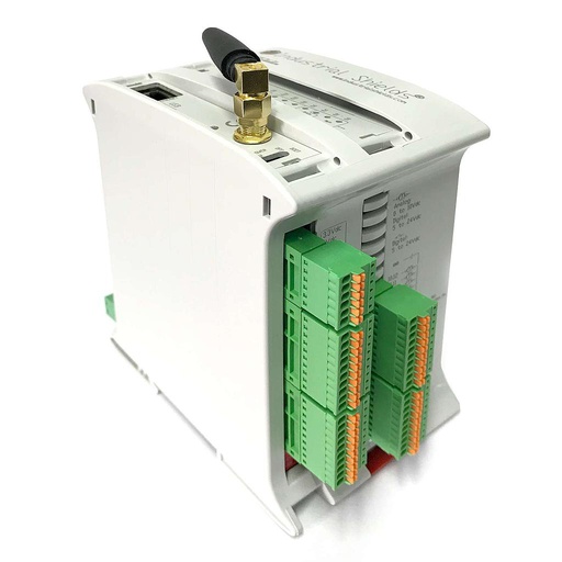
ESP32 PLC 21 FLEX
An industrial controller built on the dual-core ESP32, programmed with the Arduino IDE. The FLEX version takes one communication board: here, LoRa for the EU868 band. At a pumping station it reads the level and the pump signals, drives the pump contactors through interposing relays, and sends the LoRaWAN frames.
- Role
- Remote point: local pump control, LoRaWAN frames
- Inputs
- 13: 6 analog/digital (0-10 V, 11-bit), 7 digital optoisolated (5-24 Vdc)
- Outputs
- 8: 3 analog/digital/PWM (0-10 V), 5 digital optoisolated (5-24 Vdc)
- Comms
- Ethernet, Wi-Fi, Bluetooth LE, RS-485, RS-232
- Option board
- One: LoRa (EU, US or Asia band), 4G LTE-M/NB-IoT or CAN
- Clock
- DS3231 real-time clock with backup battery
- Programming
- Arduino IDE
- Power, mounting
- 12 to 24 Vdc, DIN rail TS35, IP20
In the project behind this case, the remote points use the ESP32 PLC 21 with the LoRa (EU868) board. A two-pump station like the one in stage 1 needs about 6 of its 13 inputs: the level, two run signals, two fault signals and a high level float. The outputs have no relays: drive the contactor coils through interposing relays.

Panel HMI Touch Screen
The screens for the operators: a capacitive touch panel at the site cabinet, and a large one in the control room.
- Role
- Local plant view, control room screen
- Sizes
- 7", 10.1" or 18.5"
- Touch
- Capacitive
- Front
- Standard or IP65
In the project behind this case: 10.1" panels with an IP65 front at the sites, and 18.5" panels in the control room.
Questions about this case
How does telecontrol of a municipal water network work?
Each site has its own PLC that controls it on site: pumps, levels, alarms. The PLC sends its values to a control room. Here, the small remote points use LoRaWAN, and the treatment plant uses MQTT over Ethernet or 4G. The control room shows all the sites, keeps the history and sends the alarms. If the network fails, each site keeps working. See the dual pump station with LoRaWAN telemetry example and the water pumping project pack.
LoRaWAN or 4G for a pumping station?
LoRaWAN fits small, periodic data: a level, the pump states, the alarms. It needs no SIM card per site and has a long range, but frames are short and airtime is limited (1 % on the main EU868 channels). A command to a Class A device waits for its next uplink. 4G fits a site that needs more data, remote programming or a fast command path, or that no gateway reaches. The Raspberry PLC 42 and the ESP32 PLC 21 take either board.
What happens when a site loses its radio link?
The site keeps controlling its pumps, because the logic runs in the PLC, not in the control room. The control room marks the site as stale after a set number of missed periods, and the frame counter shows how many frames were lost. A typical way to keep the data: log the readings on local storage and send them later. See offline-first data logging with an SD card, and try it in the Remote Site Telemetry simulator.
How do you read a 4-20 mA transmitter on a 0-10 V input?
Put a shunt resistor across the input. With 500 Ω, 4 mA gives 2 V and 20 mA gives 10 V. A reading of 3.6 mA or less means a fault (NAMUR NE 43), not a zero. To also see the high fault (21 mA or more) on a 0-10 V input, use a lower value such as 470 Ω. Use a precision resistor. See 4-20 mA level sensor reading.
Can the PLC read the drives and meters already installed?
Yes, if they speak Modbus. The Raspberry PLC 42 has two RS-485 ports for Modbus RTU and two Ethernet ports for Modbus TCP. For a serial device far from the cabinet, a serial device server puts it on the Ethernet network. Modbus TCP remote I/O modules add digital signals without new cables to the PLC. See Modbus RTU master over RS-485.
Why does the energy data of a wastewater plant matter now?
The recast Urban Wastewater Treatment Directive, (EU) 2024/3019, asks for an energy audit every four years at plants of 10,000 population equivalent and more. The first audits are due in 2028 at plants of 100,000 population equivalent and more, and in 2032 at the others. The directive also sets a national path to energy neutrality by 2045. A telecontrol network that already reads the energy meters over Modbus gives part of the data for those audits, site by site.
Download the case study
4-page PDF with the challenge, the logic, the architecture and the hardware. No form required.
Similar network?
Tell us your sites and your signals. An engineer will answer.
Tell us what kind of sites you have, what each one measures and controls, the distances, and which network reaches them today. We will tell you which controller fits each site and how to bring the data to one control room.
- You get an answer from our technical team
- One controller per site, sized by its I/O
- LoRaWAN, 4G, Ethernet and Modbus