Case study · Machine maintenance · M-Duino
Watch the machine. Plan the maintenance.
An M-Duino PLC reads the machine. MySQL keeps the history for maintenance.
The PLC reads the encoders and the sensors. The data goes to the panel, to MySQL and to maintenance.
Live data for the operator, history for the maintenance team.
This case describes how to monitor a production machine for preventive and predictive maintenance with Industrial Shields equipment. It is based on a real project at a company that repairs and makes machines and spare parts for the textile industry. The case does not name the customer. The values in the panels are examples, not data from the machine.
From the field
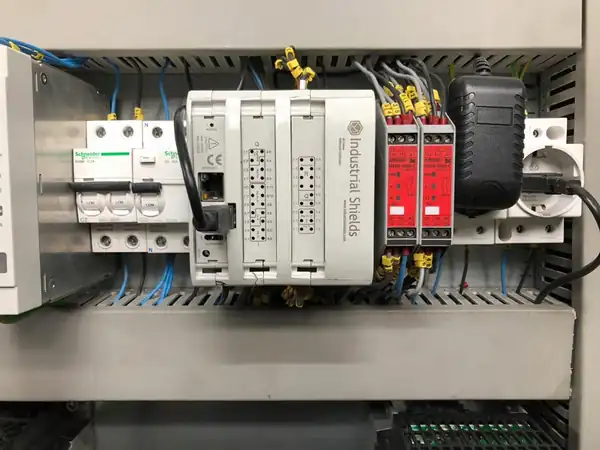
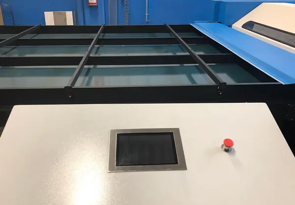
The cabinet and the machine.
Photos from the original case document.
The challenge
Turn the data of the machine into maintenance work.
The company repairs and makes machines and spare parts for the textile industry, and its engineering department builds special machines. It had two goals: make its production more efficient, and move to preventive and predictive maintenance. For that, the data of the machine had to reach the operator, a database and the maintenance planning tool.
Read the machine
Encoders and sensors on the machine already give its state. The PLC reads them and controls the state of the machine.
See it live
A Panel PC shows indicators that the customer defines. When a value passes a set limit, it raises a warning or an alarm.
Keep a history
All data goes to a MySQL database. There it is analysed to control the performance and the efficiency of the machine, and its consumption.
Plan the work
The database is connected to the planning tool for machine maintenance: preventive warnings by set limits, predictive maintenance from the history.
Alerts that reach people
Warnings and alarms are sent by email or by mobile messaging, so they also reach people who are not at the machine.
How it works
Three stages: watch, plan, predict.
Each stage shows one part of the system. Move the sliders and press the buttons. The panels are illustrative simulations: sensors, limits, intervals and trends are examples, not data from the machine.
A value passes a limit. The panel shows it and the alert goes out.
The PLC reads the encoders and the sensors of the machine and sends the data over Ethernet. On the Panel PC, the operator sees the indicators in real time. Each indicator has parameters set by the customer: past a limit, the system raises a warning or an alarm and sends it by email or mobile messaging. The PLC and the Panel PC can also act on elements of the machine. Move the sliders.
- Encoders and sensors read by the PLC
- Indicators and limits set by the customer
- Warnings and alarms by email or mobile messaging
Events (example)
Illustrative simulation. Example values, no data from the machine. Example indicator: a bearing temperature, with a warning at 65 °C and an alarm at 75 °C. The case says the customer sets the indicators and their parameters, and does not publish the sensors or the limits.
Every value goes to MySQL. Maintenance plans from it.
All the data goes to a MySQL database. There it is analysed to control performance, efficiency and consumption. The database is connected to the planning tool for machine maintenance, so preventive warnings follow the parameters set for the machine. A typical way to do it: count the run hours and warn before the service interval. Press Run one shift.
- All data in one MySQL database
- Performance, efficiency and consumption from the same rows
- Preventive warnings to the maintenance planning tool
Database and planning tool (example)
Illustrative simulation. Example values, no data from the machine. Example: one row per minute, a service every 200 run hours and a warning 24 hours before. The case says preventive warnings follow parameters set on the lines, and does not publish the intervals, the table layout or the planning tool.
The history shows where a value is going.
Some data needs analysis and a history. With the history of specific sensors, the maintenance team can do predictive maintenance and plan a stop before a value reaches its limit. The same history supports continuous improvement. Add weeks of history and watch the trend.
- History of specific sensors in MySQL
- A trend on the history (example method)
- A planned stop, not a surprise
Analysis (example)
Illustrative simulation. Example values, no data from the machine. Example indicator: a weekly vibration value in mm/s and an example limit of 7.0 mm/s. The case says predictive maintenance uses the history of specific sensors, and does not publish the sensors or the method. A typical way to do it: a trend line on the history, as here.
See alarms, downtime and OEE on a monitored line in the Machine Monitor simulator
System architecture
How does a PLC feed maintenance with machine data?
M-Duino PLCs read the encoders and the sensors of the machine and can act on its elements through their outputs. Over Ethernet, on the production network, the data goes to a Panel PC based on Raspberry Pi for live indicators, and to a MySQL database for history and analysis. The database is connected to the planning tool for machine maintenance. Warnings and alarms reach people by email or mobile messaging. The case speaks of M-Duino PLCs; the cabinet photo shows one.
| Signal | Between | Type | Purpose |
|---|---|---|---|
| Speed and position | BetweenEncoders → PLC | TypeDigital in (fast) | PurposeState of the machine. A typical way to do it: count pulses on the interrupt inputs |
| Machine sensors | BetweenSensors → PLC | TypeAnalog or digital in | PurposeValues for the indicators. The case does not publish the sensors |
| Actions on the machine | BetweenPLC → machine elements | TypeDigital or relay out | PurposeControl actions decided with the Panel PC |
| Live indicators | BetweenPLC → Panel PC | TypeEthernet | PurposeReal-time monitoring at the machine, warnings and alarms |
| All the data | BetweenPLC → MySQL | TypeEthernet | PurposeHistory; performance, efficiency and consumption |
| Maintenance data | BetweenMySQL → planning tool | TypeDatabase link | PurposePreventive warnings and predictive maintenance |
| Alerts | BetweenSystem → people | TypeEmail, mobile | PurposeWarnings and alarms away from the machine |
Why it works
One data path, from the sensor to the work order.
One path for the data
Encoders and sensors, PLC, MySQL, planning tool: the same data serves the live view, the analysis and the maintenance plan.
Two time scales
Live indicators on the panel for the operator. History in the database for analysis and planning.
Indicators that the customer sets
The customer customises the indicators and adjusts the parameters that trigger warnings and alarms.
Alerts away from the machine
Email or mobile messaging: a warning also reaches people who are not at the machine.
Preventive and predictive
Preventive warnings by set parameters. Predictive maintenance from the history of specific sensors.
Open to change
The PLC is programmed with the Arduino IDE. When the machine changes, you change the I/O or the program.
Hardware used
A PLC at the machine. A Panel PC on its housing.

M-DUINO ETHERNET PLC ARDUINO 38AR
An industrial PLC built around an original Arduino Mega 2560, with Ethernet, RS-485 and RS-232, for DIN rail. It is programmed with the Arduino IDE. On this machine it reads the encoders and the sensors, can act on machine elements through its outputs, and sends the data over Ethernet to the Panel PC and to the database.
- Role
- Encoders and sensors, actions on the machine, data to the network
- Inputs
- 19: 10 analog/digital (0-10 V, 10-bit), 9 digital optoisolated (5 to 24 Vdc), 4 with interrupt
- Outputs
- 19: 6 analog/digital/PWM (0-10 V), 5 digital optoisolated, 8 relays (230 Vac 4 A / 24 Vdc 2 A, resistive)
- Communications
- Ethernet (W5500, RJ45), RS-485, RS-232, I2C, SPI
- Built in
- Real-time clock, microSD slot
- Programming
- Arduino IDE
- Power supply
- 12 to 24 Vdc
- Mounting
- DIN rail TS35, IP20
The text of the case names M-Duino PLCs and does not fix the model. The PLC in the cabinet photo has two I/O zones, one with relay outputs. The terminal labels in the photo (I0.0 to I0.12, Q0.0 to Q0.7, R1.1 to R1.8) match the I/O map of the M-Duino 38AR, which is still in the catalogue. Size it for your machine: count the encoders, the sensors and the outputs you need. The M-Duino family has smaller and larger models.
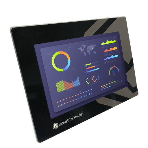
TouchBerry Pi Panel PC 10.1" FLEX
For the live view at the machine, a current option is an industrial Panel PC with a Raspberry Pi 4 and a touchscreen, connected over Ethernet. It shows the indicators in real time, raises warnings and alarms when a value passes its limit, and works with the PLC on control actions.
- Role
- Live indicators, warnings and alarms
- Screen
- 10.1", capacitive touch
- Computer
- Raspberry Pi 4
- Network
- Gigabit Ethernet
The case uses a Panel PC based on Raspberry Pi and does not publish the model or the screen size. The photo shows a panel built into the machine housing. The current family has 7", 10.1" and 18.5" models.
Questions about this case
How does a PLC help with preventive and predictive maintenance?
It reads the machine and sends the data where maintenance can use it. In this case, M-Duino PLCs read the encoders and the sensors, a Panel PC shows the indicators live, and all the data goes to a MySQL database connected to the planning tool for machine maintenance. Preventive warnings follow set parameters; predictive maintenance uses the history of specific sensors. See alarms and downtime on a monitored line in the Machine Monitor simulator.
What is the difference between the preventive and the predictive alerts here?
A preventive warning follows a parameter set in advance, such as a limit on a value or a service interval. A predictive decision comes from the history: the trend of a sensor shows when it will reach its limit, so the stop can be planned. The case uses both and does not publish its parameters or its method.
How does the PLC read encoders and sensors?
Encoders give pulses. A typical way to count them is on the interrupt inputs (the M-Duino 38AR has 4) or with an encoder module. Sensors with a 0-10 V output go to the analog inputs. For 4-20 mA, add a 500 Ω precision shunt (20 mA gives 10 V) and scale the value in the program. Contacts go to the digital inputs, 5 to 24 Vdc.
How does machine data reach the maintenance planning tool?
The case says the PLCs send the data over Ethernet to the production network, the data goes to MySQL, and MySQL is connected to the maintenance planning tool. It does not publish the software in between. A typical way to do it: a Node-RED flow or a small service on the network receives the PLC data and writes the rows. See MySQL alarm logging with Node-RED on a Raspberry Pi.
How are the alerts sent by email or to a phone?
The case sends warnings and alarms by email or by mobile messaging, and does not publish which device sends them. Two building blocks: SMTP email alerts from a monitoring server and alarm notifications with a Telegram bot in Node-RED.
Which controller should I choose for a similar machine?
Start from the list of signals: how many encoders, how many analog and digital sensors, and which elements the PLC must act on. The M-Duino 38AR has 19 inputs (4 with interrupt) and 19 outputs with 8 relays, and Ethernet. Larger machines can use a larger M-Duino or several PLCs on the same network. Send us the signal list and an engineer will answer.
Download the case study
4-page PDF with the challenge, the logic, the architecture and the hardware. No form required.
Similar machine?
Tell us your machine and what maintenance needs to know.
Tell us which encoders and sensors your machine has, which values the operator must see, which alerts maintenance needs and where your data must go. We will tell you which controller fits and how to connect it.
- You get an answer from our technical team
- I/O count and controller sizing for your machine
- Arduino, ESP32 or Raspberry Pi based PLCs