Case study · Pharma · M-Duino 58
Six culture rooms. One band per batch.
Five indicators per room, M-Duino PLCs and alarms that follow each batch.
The right level for one batch is not the right level for the next.
The thresholds follow the batch, and the alarms follow the thresholds.
This case describes a monitoring system that Industrial Shields supplied to a company that develops molecules and drugs. The case does not name the company, and it does not publish readings, set points or sensor models. It gives the rooms, the indicators, the controllers and the software. Values, bands, batch profiles, delays and the wiring on this page are examples of a typical way to do it.
The challenge
Keep every culture inside its band, in six different rooms.
The molecule and drug development sector needs specific environmental conditions in its rooms to keep the quality and efficacy of its products. This company has six rooms for different types of cultures and research. A deviation can interfere with a study, or force it to discard a whole batch. Cultures like these take a large investment of materials and people.
Temperature is critical
In storage and culture, the temperature thresholds must stay stable, so as not to interfere with the study and to avoid discarding entire batches.
Humidity in most tests
Moisture is the other key indicator during the process of the vast majority of tests.
CO2: rarely wrong, costly to fix
CO2 can affect these processes a lot. It rarely changes, but the equipment that keeps it in range is usually very expensive. So its monitoring must be fast and reliable.
Light and pressure, where they count
Light is not present in every process, and some need special light conditions. Small batches in small spaces are rarely affected by pressure, so one sensor was installed as a sample.
Levels that change with each batch
The necessary levels are not a constant. The system has to compare each reading with the thresholds of the batch that is in the room at that moment.
How it works
Three stages: measure, compare, record and warn.
Each stage shows one part of the system. Press the buttons and move the slider. The panels are illustrative simulations: rooms, values, bands and delays are examples, not data from the installation.
Each room reports its indicators to an M-Duino 58.
Sensors made for clean room use measure each room. The M-Duino 58 reads them with a program written in the Arduino IDE and keeps the latest value of each indicator. Pick a room: not every room needs every sensor.
- Temperature, humidity and CO2 in every room
- Light where the process uses it
- One pressure sensor as a sample
Readings (example)
Illustrative simulation. Example values, no data from the installation. Which rooms have a light sensor, and the room with the pressure sample, are examples. The case says that light is not present in every process and that one pressure sensor was installed as a sample.
The band comes from the batch, not from the room.
Node-RED compares each reading with the thresholds of the batch or product in the room. When a new batch comes in, its thresholds replace the old ones. Move the slider, then change the batch profile.
- One set of thresholds per batch or product
- A warning before the limit, an alarm at the limit
- The thresholds change when the batch changes
Room 2 (example)
Illustrative simulation. Example values, no data from the installation. Example bands, not the set points of the installation: A 20.0 to 22.0 °C, B 22.0 to 25.0 °C, C 18.0 to 20.0 °C. The warning comes 0.5 °C before each limit. The same reading can be fine for one batch and an alarm for the next.
Every reading is recorded. Every deviation is shown.
The Node-RED application records the readings of all the rooms and shows them on medical-grade touch screens. Warnings and alarms appear there. A typical way to close the loop: an operator acknowledges each alarm. Start an event, then acknowledge the alarm.
- A time-stamped record of every reading
- Alarms on the touch screens
- A sensor fault is an alarm too
Alarm log on the touch screen (example)
Illustrative simulation. Example values, no data from the installation. Example rules: one reading every 10 s, an alarm after 3 readings in a row out of the band, and a sensor alarm at once when the signal leaves its range. Time runs fast: one second is one reading.
System architecture
How do PLCs monitor pharmaceutical culture rooms?
Sensors in each of the six rooms measure temperature, humidity and CO2, and light and pressure where they are needed. Several M-Duino 58 PLCs read them. A typical way: transmitters with a 0 to 10 V output on the analog inputs, or digital sensors on RS-485. Over Ethernet, a Node-RED application gets the readings of all the rooms, compares them with the thresholds of each batch or product, records them and shows the warnings and alarms on medical-grade touch screens.
| Signal | Between | Type | Purpose |
|---|---|---|---|
| Temperature and humidity, each room | BetweenRoom sensors → M-Duino 58 | TypeAnalog 0-10 V | PurposeThe two key indicators of storage and culture (typical way) |
| CO2, each room | BetweenCO2 sensor → M-Duino 58 | TypeAnalog or RS-485 | PurposeA fast, reliable reading of a costly variable |
| Light, where used | BetweenLight sensor → M-Duino 58 | TypeAnalog 0-10 V | PurposeSpecial light conditions of some processes |
| Pressure, sample point | BetweenPressure sensor → M-Duino 58 | TypeAnalog 0-10 V | PurposeObserve if it affects the batches; ready for more points |
| Readings of all rooms | BetweenM-Duino 58 → Node-RED | TypeEthernet | PurposeModbus TCP or MQTT (typical way) |
| Thresholds of each batch | BetweenInside Node-RED | TypeProfile | PurposeWarnings and alarms per batch or product |
| Record | BetweenNode-RED → database | TypeHistory | PurposeEvery reading with its time (typical way) |
| Dashboard and alarms | BetweenNode-RED → touch screens | TypeEthernet | PurposeValues, warnings, alarms and acknowledge |
Why this design
Simple signals, thresholds that move.
Thresholds per batch
The levels are not a constant. Keeping the thresholds per batch or product, not per room, is what lets the alarms follow the work in the room.
Several PLCs, one picture
Each M-Duino 58 reads the rooms near it. Node-RED brings all of them into one dashboard and one record.
Fast where it costs most
CO2 rarely changes, and fixing it is expensive. A short alarm delay and a check of the sensor signal give a fast, reliable answer.
Industrial inputs for room sensors
Sixteen 0 to 10 V analog inputs per PLC read standard transmitters, and RS-485 adds digital sensors.
Ready for the future
The pressure sample shows if more points are worth it. The system is modular: add sensors, inputs or a PLC when the rooms need them.
Open tools and support
The Arduino IDE for the PLCs and Node-RED for the application. Our team supports the project before, during and after the installation, by phone, mail or WhatsApp.
Hardware
M-Duino 58 PLCs, one or more per group of rooms.
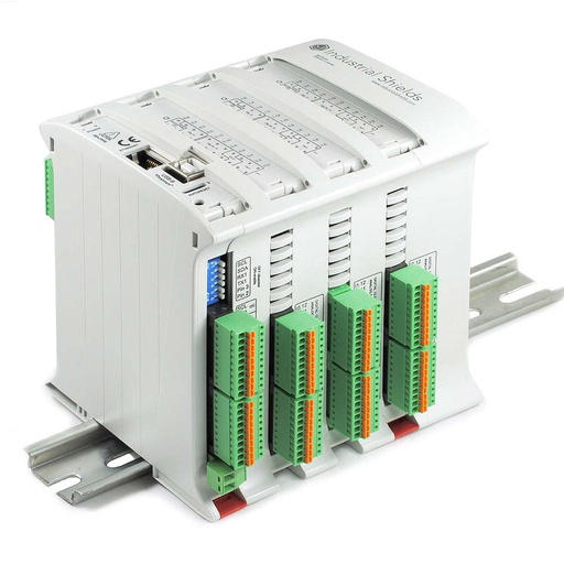
M-DUINO ETHERNET PLC ARDUINO 58
An industrial PLC built around an original Arduino Mega 2560, with 36 inputs and 22 outputs, Ethernet, RS-485, RS-232, I2C, a real-time clock and a microSD slot, for DIN rail. In this case, several of them read the room sensors and pass the values to the Node-RED application.
- Role
- Read the room sensors, send the values over Ethernet
- Inputs
- 36: 16 analog/digital (0-10 V, 10-bit), 20 digital optoisolated (5 to 24 Vdc)
- Outputs
- 22: 8 analog/digital/PWM (0-10 V), 14 digital optoisolated (5 to 24 Vdc)
- Comms
- Ethernet 10/100 (W5500), RS-485, RS-232, TTL serial, I2C, SPI
- Built in
- Real-time clock, microSD slot
- Programming
- Arduino IDE with the Industrial Shields boards package
- Power and mounting
- 12 to 24 Vdc, DIN rail TS35, IP20, 0 to 60 °C
The case calls it the M-Duino Arduino PLC 58+. It uses several of them and does not say how many, nor how the rooms are split between them. The sensors are models for clean room use, and the screens are medical-grade touch screens; the case does not name either. A typical way to wire: transmitters with a 0 to 10 V output on the analog inputs; for 4 to 20 mA transmitters, a precision resistor that turns the current into a voltage; digital sensors on RS-485 with Modbus RTU. The PLC goes in a cabinet (IP20), outside the clean area, with only the sensors in the room.
Questions about this case
How do you monitor the environment of pharmaceutical culture rooms with a PLC?
Put sensors for temperature, humidity and CO2 in each room, and light and pressure where the process needs them. Wire them to an industrial PLC such as the M-Duino 58, which reads them and sends the values over Ethernet. In this case, a Node-RED application records every reading, compares it with the thresholds of each batch or product, and shows the warnings and alarms on medical-grade touch screens.
Why set the alarm thresholds per batch and not per room?
Because the right level depends on what is in the room. The case says that the necessary levels are not a constant and must follow the thresholds of each batch at any given time. A typical way: keep a table of batch profiles in Node-RED, link each room to the batch it holds, and switch the thresholds when the batch changes. Record the change with the readings, so the history shows which band applied at each moment. See alert levels for several PLCs in Node-RED.
Why monitor CO2 if it rarely changes?
Because a CO2 deviation can affect the cultures a lot, and the equipment that keeps CO2 in range is usually very expensive. So the monitoring must be fast and reliable. A typical way: a short alarm delay for CO2, and a separate alarm when the sensor signal leaves its normal range, so a broken sensor is not read as a good value.
Does a culture room need a pressure or air flow sensor?
Often not. The case explains that cultures usually work with small batches kept in small spaces, which are rarely affected by pressure or air flow. Here one pressure sensor was installed as a sample, to see if it affects the batches, and to have the installation ready to add more points in the future.
How many room sensors can one M-Duino 58 read?
It has 16 analog inputs for 0 to 10 V signals, plus RS-485 for digital sensors. With one analog transmitter per indicator, three rooms with five indicators use 15 inputs. The case uses several M-Duino 58 and does not say how the rooms are split between them. See a Modbus TCP register map for a whole plant on an M-Duino.
Does a system like this meet GMP rules for electronic records?
The case does not say. The PLCs and Node-RED measure, record and raise alarms. If your records fall under rules such as EU GMP Annex 11 or FDA 21 CFR Part 11, the computerised system also needs validation, user access control, an audit trail and protected records. Plan them with your quality team before you start. See alarm history in a database with Node-RED.
Download the case study
4-page PDF with the challenge, the logic, the architecture and the hardware. No form required.
Similar project?
Tell us your rooms and your batches. An engineer will answer.
Tell us how many rooms you have, what you measure in each, how your thresholds change from batch to batch, and where the alarms and the records must go. We will tell you which controllers fit, and how to wire the sensors.
- You get an answer from our technical team
- Inputs, sensor signals and alarm logic for your rooms
- Arduino, ESP32 or Raspberry Pi based PLCs