Technical Features
ESP32 PLC 14
Initial installation
Arduino IDE
Arduino IDE is the original platform to program Arduino boards. This cross-platform application is available on Windows, macOS and Linux under the GNU General Public License. Arduino IDE supports C and C++ code structuring.
Industrial Shields recommends using the Legacy Arduino IDE (1.8.X) to program ESP32 based PLCs, although other ESP compatible software could be used. The Arduino 1.8.X IDE can be downloaded from this link.
After downloading and installing the Arduino IDE, install the industrialshields-esp-32 board package inside the IDE. This can be done by following this tutorial and selecting the industrialshields-esp-32 package in step number 6.
Power supply
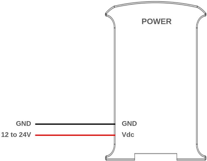
The 14 I/Os PLC based on ESP32 can be powered between 12-24V, and have a consumption between 700mA and 1500mA. Therefore, we recommend a power supply capable of supplying at least 2A. Any industrial power supply will be a good choice to power the PLCs.
Remember: Our units are designed to be powered between 12-24V. Just powering them with the USB, the unit will not be able to perform properly. The USB should be used to program the PLCs only, not to power them.
Next, a simple diagram is shown to see how to connect a power supply to any Industrial Shields unit.
Power consumption
This report explores how different Raspberry PLC models consume power
during idle and high-output scenarios. Understanding these patterns is
crucial for optimizing efficiency in industrial applications.
Resting
In this scenario, the Raspberry PLC is powered on, with all pins and communications turned off. This test measures the baseline power consumption when the device is idle and not actively engaged in any processing or output tasks.
VOLTAGE (V) | CURRENT (mA) | POWER (W) |
24 | 42 | 1,008 |
All outputs HIGH
For this test, the Raspberry PLC is configured to set all its output pins to a high state, drawing the maximum current for output operations This provides insights into the power consumption when the device is actively driving output signals.
VOLTAGE (V) | CURRENT (mA) | POWER (W) |
24 | 81 | 1,944 |
Inputs & Outputs
Analog inputs
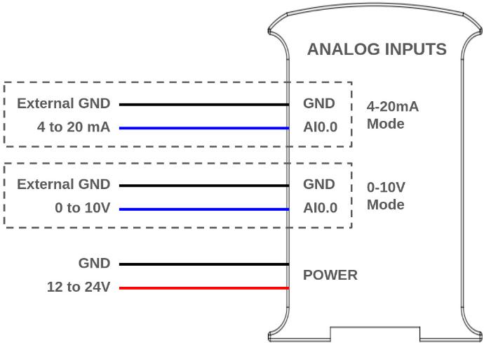
Analog input provides a way to read analog voltage levels, coding the value with an N-bit number. The analog inputs on the 14 I/Os PLC use the internal GND for reference (the same as the power supply). Additionally, the analog inputs can also be used as non isolated digital inputs tolerating up to 24Vdc.
Note that the analog input values are lineal in all range between 1V and 10V when using 0-10V mode as the resolution is approximately 11.5 bits just like when using the 4-20mA mode.
Note: The analog inputs have a resolution of 11.507 bits counting from 0 to 10Vdc and the first 1V (0-1Vdc -> 0 - 291) range is not linear but the second one 9V (1-10Vdc -> 291 - 2910) range is linear.
The 14 I/Os PLC provides 2 analog inputs (AI0.0 and AI0.1) which can be used with both modes (0-10V and 4-20mA).
Typical connection
The following diagram illustrates an example connection:
Software setup
The analog inputs must be configured in the set up part of the code, like it is usually done in common Arduino boards.
void setup() {
  pinMode(I0_7, INPUT);
  Serial.begin(9600);
}

void loop() {
  Serial.println(analogRead(I0_7));
}
Digital inputs
Digital inputs are used to capture signals that exist in one of two
states: high or low, true or false, etc. The 14 I/Os digital inputs
interpret as high values of 3.3 Vdc or higher, up to 24 Vdc, whereas
values lower than 3.3V are interpreted as low. All the digital inputs
from the 14 I/Os are optoisolated and the resolution is of 10 bits.
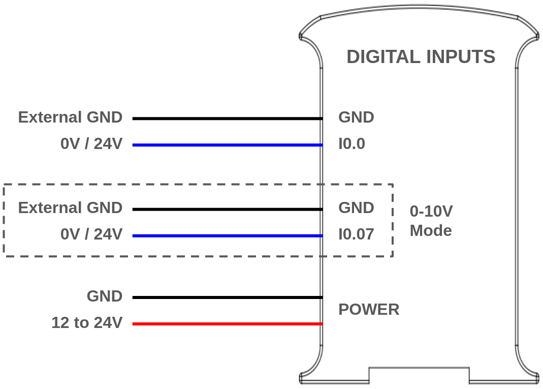
The 14 I/Os PLC provides 9 digital inputs (from I0.0 to I0.8).
Note: Pins I0.7 and I0.8 serve different functions based on the selected mode.
Typical connection
The following diagram illustrates an example connection:
Software setup
The digital inputs must be configured in the set up part of the code, like it is usually done in common Arduino boards.
void setup() {
  pinMode(I0_0, INPUT);
  Serial.begin(9600);
}

void loop() {
  Serial.println(digitalRead(I0_0));
}Digital outputs
The 14 I/Os digital outputs can provide a low (0 Vdc) or high (up to 24 Vdc) value. The output high value can range between 3.3 and 24 Vdc whereas
values lower than 3.3V are interpreted as low, all the digital inputs are optoisolated.
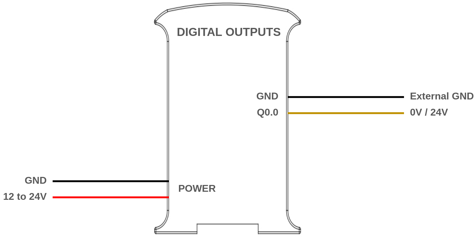
The 14 I/Os PLC provides 4 digital outputs (from Q0.0 to Q0.3).
Typical connection
The following diagram illustrates an example connection:
Software setup
The digital outputs must be configured in the set up part of the code, like it is usually done in common Arduino boards.
void setup() {
  pinMode(Q0_0, OUTPUT);
}

void loop() {
  digitalWrite(Q0_0, HIGH);
  delay(1000);
  digitalWrite(Q0_0, LOW);
  delay(1000);
}
As the digital outputs can take values of 5V and 24V, it needs to be set up. For more information check this post.
Relay output
A relay is an electromagnetic switch controlled by an electric signal. In Industrial Shields units these devices are already integrated in their boards. The relay included in the 14 I/Os PLC have the following specifications:
- Maximum DC current: 3A at 30Vdc.
- Maximum AC current: 5A at 250Vac
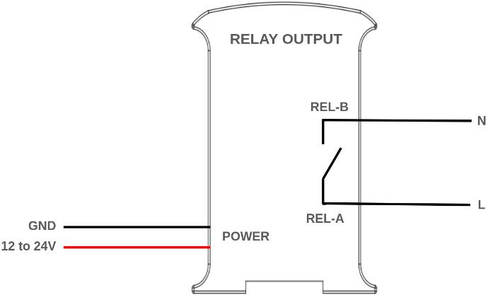
The 14 I/Os PLC provides 1 relay output where the terminals are REL-A and REL-B.
Typical connection
The following diagram illustrates an example connection:
Software setup
The relay output must be configured in the set up part of the code, like it is usually done in common Arduino boards.
void setup() {
  pinMode(R0_1, OUTPUT);
}

void loop() {
  digitalWrite(R0_1, HIGH);
  delay(1000);
  digitalWrite(R0_1, LOW);
  delay(1000);
}
Communications
Ethernet
Ethernet is the technology that is most commonly used in wired local area networks ( LANs ).
A LAN is a network of computers and other electronic devices that covers a small area such as a room, office, or building. It is used in contrast to a wide area network (WAN) , which spans much larger geographical areas. Ethernet is a network protocol that controls how data is transmitted over a LAN. Technically it is referred to as the IEEE 802.3 protocol. The protocol has evolved and improved over time to transfer data at the speed of a gigabit per second.
Our 14 I/Os PLC incorporate the integrated W5500 IC.
WX5500 is a Hardwired TCP/IP embedded Ethernet controller that provides easier Internet connection to embedded systems. This chip enables users to have Internet connectivity in their applications by using the single chip in which TCP/IP stack, 10/100 Ethernet MAC and PHY are embedded. The W5500 chip embeds the 32Kb internal memory buffer for the Ethernet packet processing. With this chip users can implement the Ethernet application by adding the simple socket program. SPI is provided for easy integration with the external microcontroller.
Example code
This code serves as a diagnostic tool to ensure the proper functioning of the Ethernet feature on your 14 I/O PLC. It establishes a connection to "www.google.com" through the W5500 controller using DHCP IP configuration. Before running the code, ensure that your PLC is powered correctly, confirm that the Ethernet cable is securely connected to your device and make sure the "industrialshields-esp-32" board package is properly installed in your Arduino IDE.
#include <Ethernet.h>

#define REMOTE "www.google.com"

const uint16_t port = 80;
uint8_t mac[] = {0xAA, 0xBB, 0xCC, 0xDD, 0xEE, 0x01};

EthernetClient c;

////////////////////////////////////////////////////////////////////////////////////////////////////
void setup() {
  Serial.begin(9600L);
  Serial.println("ethernet started");

  test();
}

////////////////////////////////////////////////////////////////////////////////////////////////////
void loop() {
  if (!c.connected()) {
    Serial.println("Disconnected");
    test();
  }
  delay(1000);
}

////////////////////////////////////////////////////////////////////////////////////////////////////
void test() {
  //if you need a DHCP IP use this configuration:
  Ethernet.begin(mac);

  switch (Ethernet.hardwareStatus()) {
    case EthernetW5100:
      Serial.println("W5100 found");
      break;

    case EthernetW5200:
      Serial.println("W5200 found");
      break;

    case EthernetW5500:
      Serial.println("W5500 found");
      break;

    default:
      Serial.println("Unknown hardware");
      break;
  }

  uint8_t MAC[6];
  Ethernet.MACAddress(MAC);
  for (int i = 0; i < 6; ++i) {
    if (i > 0) {
      Serial.print(':');
    }
    Serial.print(MAC[i], HEX);
  }
  Serial.println();

  //use this block with DHCP IP:
  Serial.println(Ethernet.localIP());
  if (Ethernet.localIP() == IPAddress({0,0,0,0})) {
    Serial.println("Local IP FAIL");
  } else {
    Serial.println("Local IP OK");
    if (c.connect(REMOTE, port)) {
      Serial.println("Remote connection OK");
    } else {
      Serial.println("Remote connection FAIL");
    }
   }
}
RS-485
RS485 also known as TIA-485(-A), EIA-485, is a standard defining the electrical characteristics of drivers and receivers for use in serial communications systems. Electrical signaling is balanced, and multipoint systems are supported.
Our 14 I/Os PLC incorporate the integrated circuit MAX485.
MAX485 is a low-power and slew-rate-limited transceiver used for RS-485 communication. It works at a single +5V power supply and the rated current is 300 μA. Adopting half-duplex communication to implement the function of converting TTL level into RS-485 level, it can achieve a maximum transmission rate of 2.5Mbps. MAX485 transceiver draws supply current of between 120μA and 500μA under the unloaded or fully loaded conditions when the driver is disabled.
The 14 I/Os support half duplex RS-485 communications.
Example code
This code establishes straightforward communication between two devices using the RS485 protocol. Data written from the serial interface in one device is transmitted to the other via RS485. Load this code onto the 14 I/O PLC and another device with RS485 communication capabilities (such as any of our PLCs). Connect them by matching A+ with A+ and B- with B-. Before running the code, ensure that your PLC is powered correctly, verify that the RS485 cables are securely connected to the devices, and confirm that the "industrialshields-esp-32" board package is correctly installed in your Arduino IDE.
#include <RS485.h>

void setup() {
  // Begin Serial port
  Serial.begin(9600);
  // Begin RS485 port
  RS485.begin(9600, HALFDUPLEX);
}

void loop() {
  //Send one byte for the serial, receive this byte by rs485
  if (Serial.available()){
    read_from_serial();
  }
  if (RS485.available()){
    read_from_rs485();
  }
}

static void read_from_serial(void){
  char tx = Serial.read(); //Read byte
  if (tx != '\n') Serial.println(tx); //Print the byte
  RS485.write(tx); //Transmit by rs485
}

static void read_from_rs485(void){
  char rx = RS485.read(); //Receive the same byte
  if (rx != '\n') {
    Serial.println(rx); //Print the byte
  }
}
I2C
I2C is a synchronous protocol which uses 2 cables, one for the clock (SCL) and one for the data (SDA). This means that the master and the slave send data through the same cable, which is controlled by the master, who also creates the clock signal. I2C does not use slave selection, but addressing.
I2C is a serial communications protocol. The speed is 100 Kbit/s in standard mode, but it allows speeds of up to 3.4 Mbit/s. It is a very used bus in the industry, mainly to communicate microcontrollers and their peripherals in integrated systems. It is also used to communicate integrated circuits among themselves, normally residing in a same PCB (printed circuit board).
Example code
This code utilizes the "Wire.h" library to implement an I2C scanner, scanning the I2C-bus for devices. When a device is detected, it will be reported to the serial monitor. Before running the code, ensure that your PLC is powered correctly, confirm that the "Wire.h" library is installed in your Arduino IDE, and verify that the "industrialshields-esp-32" board package is correctly installed in your Arduino IDE.
Note that if you connect the I2C pins (SDA and SCL) to an other device, it should appear in the scan.
#include "Wire.h"

void setup() {
  Serial.begin(115200);
  Wire.begin();
}

void loop() {
  byte error, address;
  int nDevices = 0;

  delay(5000);

  Serial.println("Scanning for I2C devices ...");
  for(address = 0x01; address < 0x7f; address++){
    Wire.beginTransmission(address);
    error = Wire.endTransmission();
    if (error == 0){
      Serial.printf("I2C device found at address 0x%02X\n", address);
      nDevices++;
    } else if(error != 2){
      Serial.printf("Error %d at address 0x%02X\n", error, address);
    }
  }
  if (nDevices == 0){
    Serial.println("No I2C devices found");
  }
}
Bluetooth
Bluetooth is a another wireless technology standard. Bluetooth was developed as a way to exchange data over a short range. Operates in the 2400-2483.5 MHz range within the ISM 2.4 GHz frequency band. Data is split into packets and exchange through one of 79 designed Bluetooth channels (each of which have 1 MHz in bandwidth).
If you want to know how to use Bluetooth with your 14 I/Os you can check this guide.
Wi-Fi
Wi-Fi is one of the most important technological developments of the modern age. Similar to other wireless connection types, like Bluetooth, it's a radio transmission technology built upon a set of standards to allow high-speed and secure communications between a wide variety of digital devices, access points and hardware. It makes it possible for Wi-Fi capable devices to access the internet without the need for wires. It can operate over short and long distances, be locked down and secured, or open and free. It's incredibly versatile and easy to use.
Example code
This code uses the "WiFi.h" library to connect the 14 I/Os to your desired Wi-Fi. It reports to the serial monitor the IP address used to connect. Before running the code, ensure that your PLC is powered correctly, confirm that the "WiFi.h" library is installed in your Arduino IDE, and verify that the "industrialshields-esp-32" board package is correctly installed in your Arduino IDE.
Make sure to change the ssid and password variables to your desired Wi-Fi configurations.
#include "WiFi.h"
const char* ssid = "YOUR_SSID";
const char* password = "YOUR_PASSWORD";
void setup() {
Serial.begin(115200);
WiFi.begin(ssid, password);
while (WiFi.status() != WL_CONNECTED) {
delay(500);
Serial.print(WiFi.status());
}
Serial.println("");
Serial.print("Connected to ");
Serial.println(ssid);
Serial.print("IP address: ");
Serial.println(WiFi.localIP());
}
void loop() {
}
Extra features
14 I/Os Modes
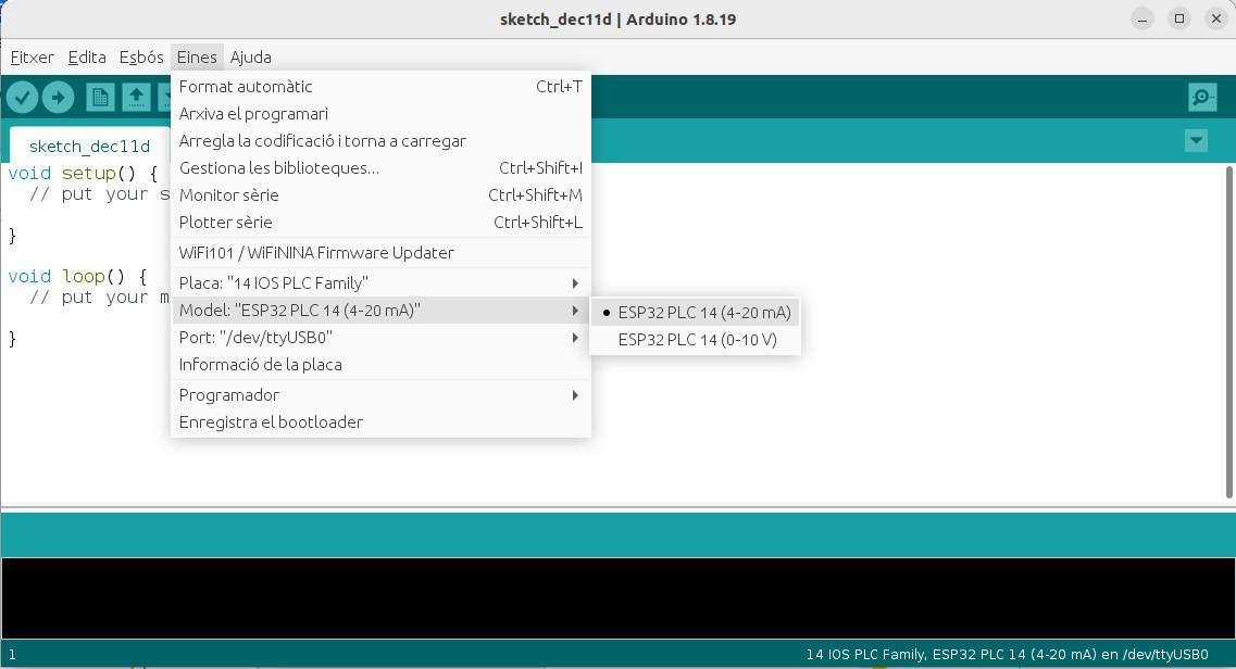
As mentioned in some sections above, the 14 I/Os PLC can be configured in 2 different modes:
- Mode 0-10V
- Mode 4-20mA
Depending on the chosen mode, the behavior of inputs pins AI0.0/I0.7 and AI0.1/I0.8 varies, as detailed below.
Configure the mode in the Arduino IDE by navigating to Tools > Model and selecting your desired mode:
ESP32 Dual Core
The ESP32 programmable logic controller include 2 Xtensa 32-bit LX6 microprocessors. When we run code on Arduino IDE, by default, it runs on core 1, as we can check with this simple program:
void setup() {
Serial.begin(115200);
Serial.print("setup() running on core ");
Serial.println(xPortGetCoreID());
}
void loop() {
Serial.print("loop() running on core ");
Serial.println(xPortGetCoreID());
}However, we can also use the second core, for better performance and efficiency. In order to work with the second core, we just need to define a second loop function, called "loop1()". The code inside this function will be executed by core 0, whereas the code inside the usual "loop()" function is executed by core 1. This way we can define different tasks for each core:
void setup() {
  // Setup code
}
void loop() {
  // Core 1 tasks
}
void loop1() {
  // Core 0 tasks
}
Organizing the program like this we can take advantage of the 2 cores in the ESP32. Some considerations need to be made when using the dual core, though, as concurrency problems may appear: for example if both try to use the Serial at the same time. In order to avoid this problems mechanisms such as sempahores might be used.
Check this blog post to know more about the ESP32 dual core.
FreeRTOS
FreeRTOS is a popular open-source real-time operating system (RTOS) designed for microcontrollers and small embedded systems. It provides a lightweight, scalable, and portable operating system kernel, along with a range of software components and tools to support the development of embedded applications. FreeRTOS can be used with the Arduino IDE on ESP32 boards to add real-time operating system functionality to your projects.
With FreeRTOS, you can create multiple tasks in your sketch, each with its own priority, and use synchronization mechanisms like semaphores and mutual exclusion to coordinate the tasks. This can be useful for real-time applications that require precise timing and coordination of tasks.
There is no need to include any library to use FreeRTOS with ESP32 based PLCs, since it is integrated into ESP-IDF as a component (Arduino leverages ESP-IDF).
One of the most useful features of FreeRTOS are tasks, schedulables pieces of code. In order to create a task the function xTaskCreate() is used.
Example code
This program creates 2 tasks to periodically set HIGH and LOW two digital outputs.
TaskHandle_t Task1;
TaskHandle_t Task2;

void setup() {
 Serial.begin(115200);
 pinMode(Q0_0,OUTPUT);
 pinMode(Q0_1,OUTPUT);

 xTaskCreate(Task1code,"Task1",10000,NULL,1,&Task1);
 delay(500);

 xTaskCreate(Task2code,"Task2",10000,NULL,1,&Task2);
 delay(500);
}

void Task1code( void * parameter ){
 Serial.print("Task1 is running on core ");
 Serial.println(xPortGetCoreID());

 for(;;){
 digitalWrite(Q0_0, HIGH);
 delay(500);
 digitalWrite(Q0_0, LOW);
 delay(500);
 }
}

void Task2code( void * parameter ){
 Serial.print("Task2 is running on core ");
 Serial.println(xPortGetCoreID());

 for(;;){
 digitalWrite(Q0_1, HIGH);
 delay(1000);
 digitalWrite(Q0_1, LOW);
 delay(1000);
 }
}

void loop() {}
