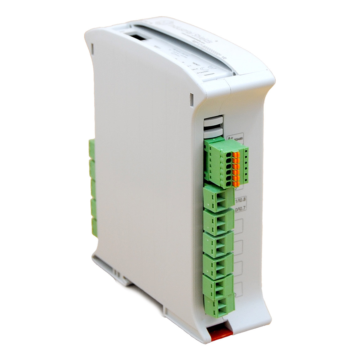
Welcome to our blog where we explore how to properly use the digital outputs on the ESP32 PLC 14. We'll be diving into practical tips and techniques to help you get started. Let's jump right in!
Requirements
Setup
The ESP32 PLC 14 features 4 digital outputs. These outputs are labelled Q0.0, Q0.1, Q0.2 and Q0.3 and can be used in two modes:
- 5V output mode.
- Vdc output mode.
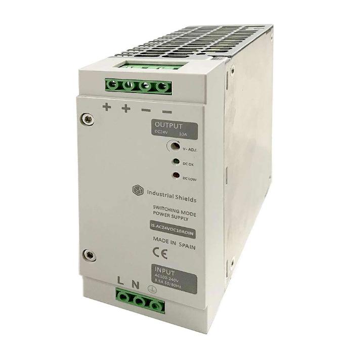
Remember! The ESP32 PLC 14 needs to be powered with a 12-24Vdc power supply. When the outputs are in Vdc mode, the outputs will work at the supplied voltage, and when they are in 5V mode they will supply, as the the name implies, 5V. The digital outputs voltage reference is the internal GND of the PLC (the same as the power supply).
Programming
Let's see how we can program the PLC to use the digital outputs. First of all, install our boards package, which provides the necessary libraries: you can do it by following this tutorial.
The first thing you we need to do in the program is select the mode in which the outputs are working. Each has an internal pin called "SX_24v", with 'X' being the number of the output. Setting the value of this pin we can select the output mode:
- Set to low to select 5V mode.
- Set to high to select Vdc mode.
The usual pinMode() and digitalWrite() Arduino functions can be used to interact with these pins. For example, to set Q0.0:
pinMode(S0_24v, OUTPUT);
digitalWrite(S0_24v, LOW); // set to 5V mode
digitalWrite(S0_24v, HIGH); // set to Vdc mode
Once the mode has been set you can interact with the digital output like a regular Arduino pin, setting it to low or high. To address the outputs in the code, use the following nomenclature, substituting the decimal point ('.') in the output name with an underscore ('_'):
- Q0.0: Q0_0
- Q0.1: Q0_1
- Q0.2: Q0_2
- Q0.3: Q0_3
Remember that first you need to configure the pin as an output:
pinMode(Q0_0, OUTPUT);
digitalWrite(Q0_0, HIGH);
Digital outputs test
Take a look at the following example sketch, where the outputs alternate between ON and OFF every 5 seconds. Two of them are set to the 5V mode, whereas the other two are in Vdc mode.
void setup() {

  pinMode(Q0_0, OUTPUT);
  pinMode(Q0_1, OUTPUT);
  pinMode(Q0_2, OUTPUT);
  pinMode(Q0_3, OUTPUT);

  pinMode(S0_24v, OUTPUT);
  pinMode(S1_24v, OUTPUT);
  pinMode(S2_24v, OUTPUT);
  pinMode(S3_24v, OUTPUT);

  delay(100);
  digitalWrite(S0_24v, LOW);
  digitalWrite(S1_24v, LOW);
  digitalWrite(S2_24v, HIGH);
  digitalWrite(S3_24v, HIGH);

}

void loop() {

  delay(5000);
  digitalWrite(Q0_0, HIGH);
  digitalWrite(Q0_1, HIGH);
  digitalWrite(Q0_2, HIGH);
  digitalWrite(Q0_3, HIGH);

  delay(5000);
  digitalWrite(Q0_0, LOW);
  digitalWrite(Q0_1, LOW);
  digitalWrite(Q0_2, LOW);
  digitalWrite(Q0_3, LOW);

}
With this program you can test the outputs in your industrial PLC. Check out how the LEDs in the top side illuminate when the outputs are set high.
Thanks for reading our post on using the digital outputs of the ESP32
PLC 14. Now you already know how to interact with the digital outputs of an ESP32 PLC 14. We hope you found it helpful for your projects, keep tinkering
and discovering new ways to make the most of this hardware.


Basic usage of the ESP32 PLC 14 digital outputs