Introduction
Nowadays, Bluetooth is one of the most used technologies in our daily lives; it appears in a lot of connections with cell phones, tablets and other different wearables. In addition, it can be used in applications related to industry, such as managing a programmable logic controller remotely. In this post, we are going to see an easy example about it.
It is very important to know that we are going to work with standard Bluetooth, not with the BLE (Bluetooth Low Energy), because we are going to see an example of this version in another post. This post is made to work with the 10 I/Os ESP32 PLC, but for the connexion and configuration of the PLC, please take a look at the Datasheet and User Guide of the product itself.
Related links
Most used communications in each Industry Sector
Read >>
How to use communication protocols in industrial automation
Read >>
10 I/Os industrial PLC Controller Family
Read >>
Programming the 10 I/Os ESP32 PLC using WiFi
Read >>
Requirements
10 I/Os ESP32 PLC
Cell phone / Tablet
BluetoothSerial.h (included in Industrial Shields libraries)
Example
Connections
The PLC has to be connected to a 12/24V power supply and connected to the PC through a microUSB cable to upload the code and use the Serial Port. Apart from that, this example uses six leds connected to six digital outputs of the PLC (so we recommend the Digital version of the PLC).
WARNING: THE LEDS HAVE TO BE COMPATIBLE WITH THE CURRENT AND VOLTAGE OF THE PLC OUTPUTS, OTHERWISE THE LEDS CAN BE DAMAGED.
Q0_0 -> led 1
Q0_1 -> led 2
Q0_2 -> led 3
Q0_3 -> led 4
Q0_4 -> led 5
Q0_5 -> led 6
Code
First of all, we include the "BluetoothSerial.h" library that allows you to work with this technology like if you were using Serial communication. After this, you should make sure that the Bluetooth is enabled with the conditional definition. We also define some more parameters and an open_all function designed to open all the leds simultaneously.
In the setup, you have to initialize the Serial baudarte, the SerialBT by writing the name of the Bluetooth device, you can configure the pins of the leds as outputs, and define a parameter for millis() function so you are going to need it.
In the loop, you make a block to open one led per time period in a row; if millis() (which count the actual loop time) - Time (defined previously) is bigger or equal to the Period (250 ms), the first conditional is entered and, in the second one, if select (initialized to 0) is lower than 7, the current led is activated and the previous one is deactivated (if not, select is reset to 0). The Time variable is updated. If the Serial port is available, the SerialBT writes anything that is read by the Serial port. If the SerialBT is availble, we receive the data by doing a SerialBT.read and, if we receive a new line ('\n'), we upload the message adding the string of the received char (otherwise the messsage will be empty). You will make a Serial.write of the received char. If the message received by the BT (PLC) is STOP and it is synchronized with a HIGH lecture of the led connected to the led_4 (Q0_3), you have won the game and all the leds open in victory signal.
 /*
   Copyright (c) 2020 Boot&Work Corp., S.L. All rights reserved

   This program is free software: you can redistribute it and/or modify
   it under the terms of the GNU Lesser General Public License as published by
   the Free Software Foundation, either version 3 of the License, or
   (at your option) any later version.

   This program is distributed in the hope that it will be useful,
   but WITHOUT ANY WARRANTY; without even the implied warranty of
   MERCHANTABILITY or FITNESS FOR A PARTICULAR PURPOSE.  See the
   GNU Lesser General Public License for more details.

   You should have received a copy of the GNU Lesser General Public License
   along with this program.  If not, see <http://www.gnu.org/licenses/>.
 */


#include "BluetoothSerial.h"

#if !defined(CONFIG_BT_ENABLED) || !defined(CONFIG_BLUEDROID_ENABLED)
#error Bluetooth is not enabled! Please run `make menuconfig` to and enable it
#endif

BluetoothSerial SerialBT;

int leds[] = {Q0_0, Q0_1, Q0_2, Q0_3, Q0_4, Q0_5};

String message = "";
char char_received;
int Period = 250;
unsigned long Time;
int select = 1;

void open_all(void){
  select = 0;
  while(select < 7){
    digitalWrite(leds[select], HIGH);
    select += 1;
  }
}

void setup() {

  Serial.begin(115200);
  SerialBT.begin("ESP32test"); //Bluetooth device name
  Serial.println("The device started, now you can pair it with bluetooth!");
  pinMode(Q0_0, OUTPUT);
  pinMode(Q0_1, OUTPUT);
  pinMode(Q0_2, OUTPUT);
  pinMode(Q0_3, OUTPUT);
  pinMode(Q0_4, OUTPUT);
  pinMode(Q0_5, OUTPUT);
  Time = millis();
}

void loop() {
if(millis()-Time>=Period){
    if (select<7){
      digitalWrite(leds[select-1], LOW);
      digitalWrite(leds[select], HIGH);
      select += 1;
    }
    else{
      select = 0;
    }
    Time = millis();
  }
  if (Serial.available()) {
    SerialBT.write(Serial.read());
  }
  if (SerialBT.available()) {
    char_received = SerialBT.read();
    if (char_received != '\n'){
      message += String(char_received);
    }
    else {
      message = "";
    }
    Serial.write(char_received);
    if (message == "STOP"){
      if (digitalRead(Q0_3) == HIGH){
        Serial.println("\nYOU HAVE WON");
        open_all();
        Time = 0;
      }
    }
  }
  delay(20);
}
Application
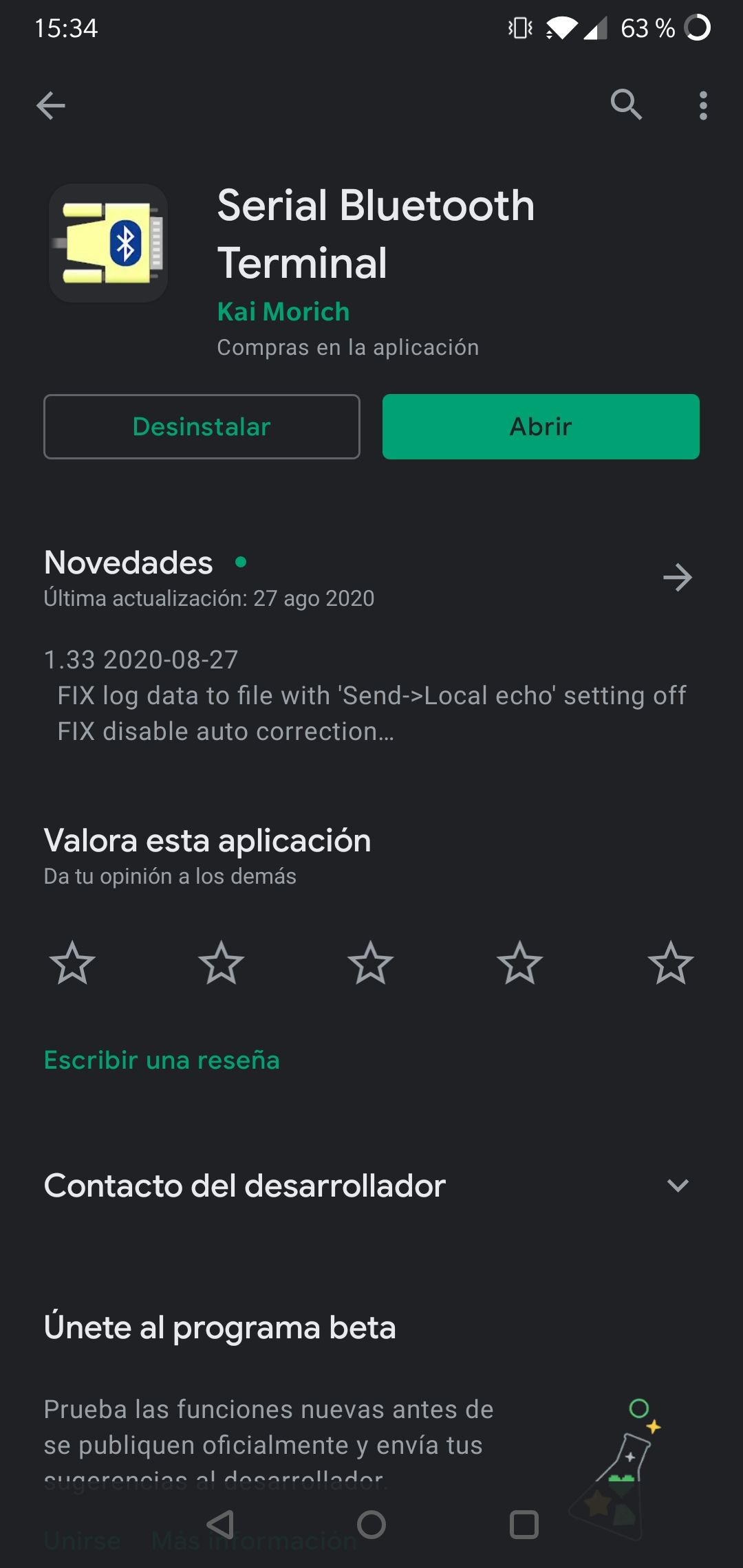
If you want to communicate with the PLC through Bluetooth, you will need, for example, a Serial Bluetooth application, like the one used in this example. The name of the app is "Serial Bluetooth Terminal©"* and you can download it on Android Market (it does not exist in Apple Store but you can find other similar ones):

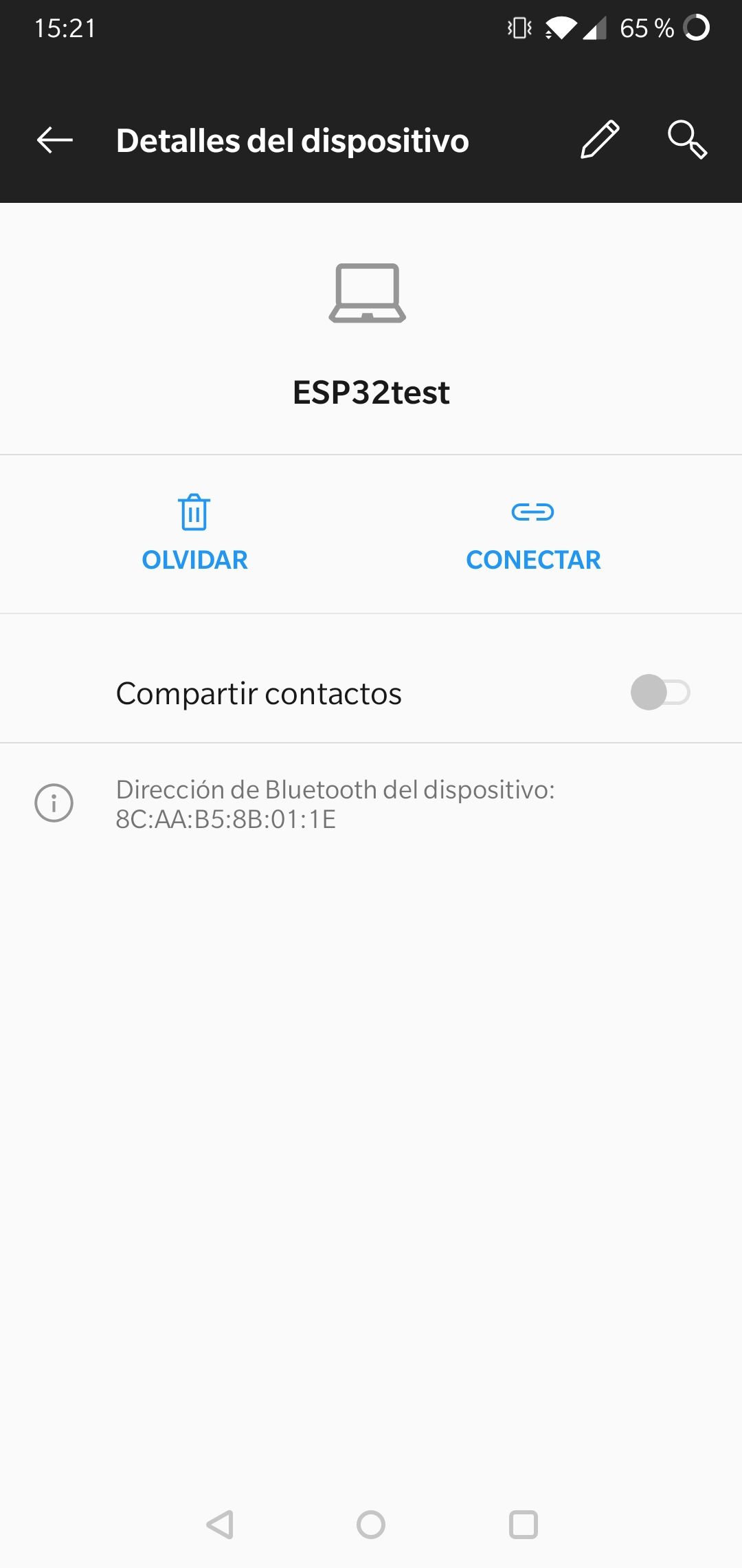
After this, you have to upload the previous code to the PLC by selecting the correct device and port. When the upload is completed, you can search the device called "ESP32test" with the Bluetooth of your mobile phone and pair it:

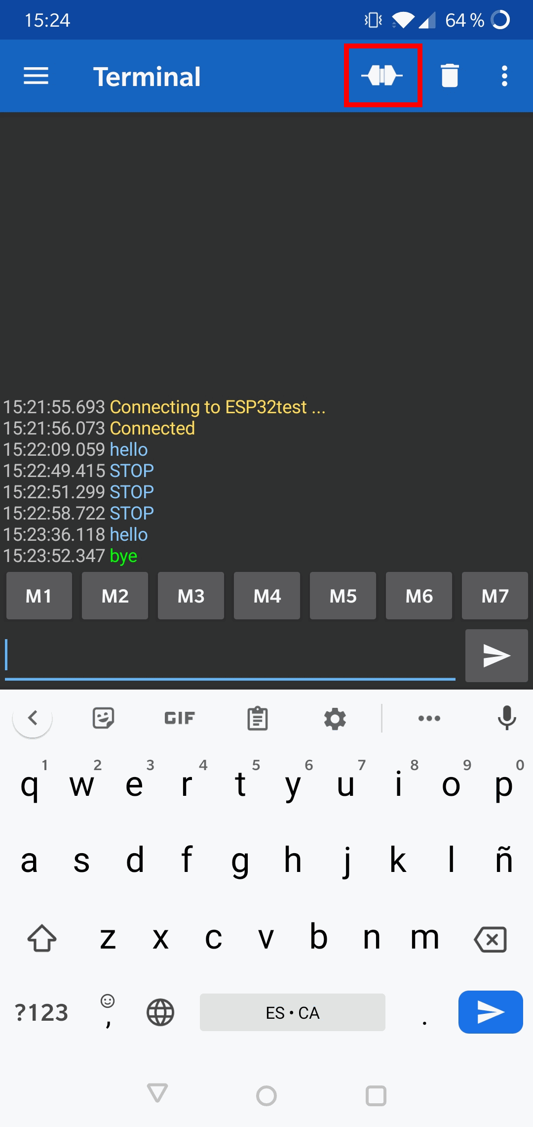
Now, you can open the app, click on the connect button in the upper right corner and you can start chatting with the Arduino IDE Serial Monitor; you can write and receive messages using the application (mobile phone) - Serial Monitor (PLC). The blue messages are the ones that you send from the app to the PLC, and the green messages are those sent from the PLC to the application:

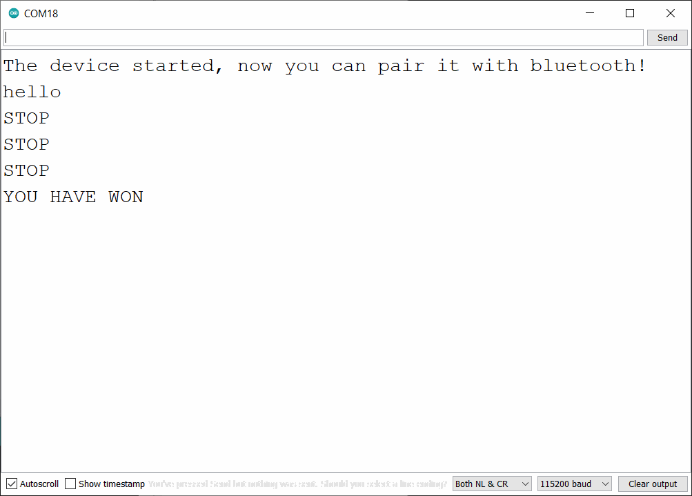
As we have explained, the game here is that the leds are going to be activated one by one, in order and, using the app, you have to write and send the word "STOP" when the fourth led is on. You can try it as many times as you want and, if you win, a message will be printed through Serial Monitor and all the leds will be activated:
* This app is created by Kai Morich ©

How to control an ESP32 industrial controller via Bluetooth