Modbus on Raspberry PLCs with Node-RED
Implementation for Raspberry based PLCs (Node-RED)
Installation
1. librpiplc implements useful functions to use Raspberry based Industrial Shields PLCs for industrial environments. This library is needed to use node-red-contrib-rpiplc-node. Follow the installation steps from here.
2. Node-RED collections: Download the following collections either with the command npm install [collection] or from the Node-RED interface on Menu button (three horizontal bars) > Manage Palette > Install tab > Search the collection to install.
- node-red-contrib-rpiplc-node is a collection of Node-RED nodes for using analog inputs, analog outputs,
digital inputs and digital outputs from Raspberry PLC of Industrial
Shields. Find more information here.
- node-red-contrib-modbus is a collection of Node-RED nodes for implementing Modbus slave and master. Find more information here.
Slave
The following JSON file contains a Node-RED Modbus TCP example:
Modbus TCP Slave
To import the example from Node-RED, go to Menu button (three horizontal bars) > Import > Select the file.
The Modbus library used from Node-RED (node-red-contrib-modbus), does not support a Modbus RTU slave implementation. Check @krakul/node-red-modbus-rtu-slave for implementing a Modbus RTU slave with Node-RED.
Implementation Guide
The flow is distributed in three groups:
The example is implemented for a Raspberry PLC 21+. To use this code for other models, the rpiplc config, read and write nodes might need to be modified.
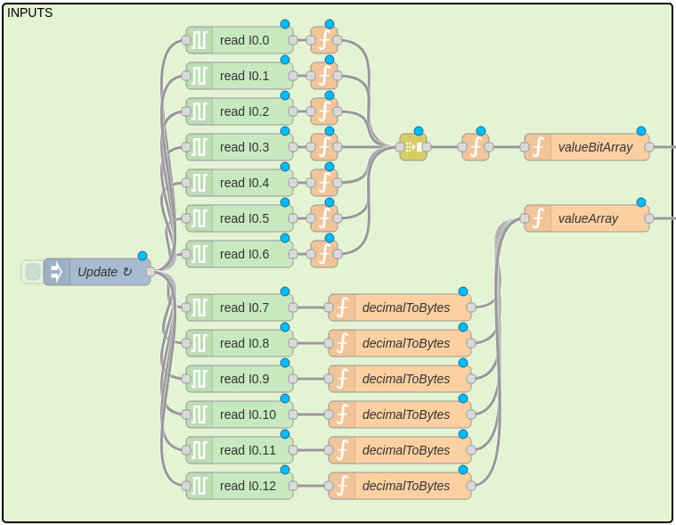
1. Inputs: The Inputs group is essential for reading digital and analog values from the PLC. It collects digital input values, representing binary states like on/off, and passes them as Discrete Inputs. It also gathers analog input values, representing continuous data like temperature or pressure, and sends them as Input Registers. These values are then forwarded to the Control group for further processing and control actions.
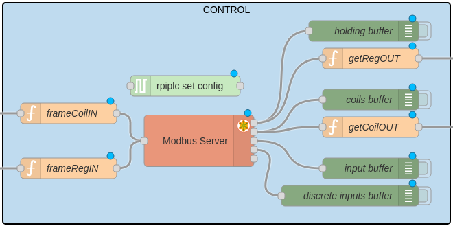
2. Control: The Control group orchestrates the PLC operations, serving as the nexus for data processing and control. It initializes the Modbus Server node and interfaces with the Inputs group to receive Discrete Inputs and Input Registers. Then forwards processed information as Coils and Holding Registers to the Outputs block for further action.
To configure the flow:
- Click on Modbus Server node to configure the Hostname, the Port and the number of each type of objects.
- Click on rpiplc set config node to configure your PLC with the Version and Model.
3. Outputs: The Outputs group receives Coils and Holding Registers from the Control group, which represent the binary and continuous output signals, respectively. Then, the digital and analog outputs of the PLC are updated.
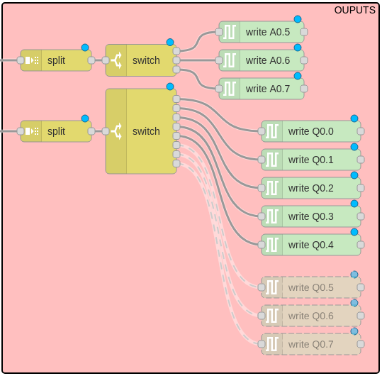
In this configuration, the nodes responsible
for writing to the digital outputs Q0.5, Q0.6, and Q0.7 are disabled.
This is due to the shared nature of these outputs with the analog
outputs. In this example, the PLC's switch is set to utilize the analog
outputs instead.
Master
The following JSON file contains Node-RED Modbus examples for both RTU and TCP:
To import the example from Node-RED, go to Menu button (three horizontal bars) > Import > Select the file.
Implementation Guide
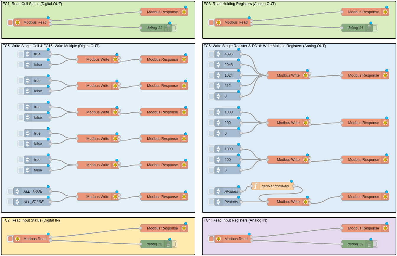
The example is structured into groups based on different Modbus function codes (FC). Each function code group contains related nodes for Modbus operations like reading coils, writing registers, etc
The only difference between the RTU and TCP implementation is the Modbus slave configuration. The configurations can be done by clicking a Modbus node and clicking on the pencil of the Server option.
- For Modbus RTU:
- Select the Serial Expert option under Type.
- Enter the serial port used in the Serial port field.
- Select the RTU-BUFFERD option under Serial type.
- Enter the configurations of the communication: Baud rate, Data bits, Stop bits and Parity.
- Enter the slave ID in the Unit-ID field.
- For Modbus TCP:
- Select the TCP option under Type.
- Enter the IP address of the slave device in the Host field.
- Specify the port number of the slave device in the Port field.
- Enter the slave ID in the Unit-ID field.
There is a group for every available Function Code:
1. FC1: Read Coil Status (Digital OUT)
- This group contains nodes for reading coil status (digital outputs) from the Modbus server.
- It includes inject nodes to trigger read requests, Modbus read nodes to read coil status, and debug nodes to display the results.
2. FC2: Read Input Status (Digital IN)
- This group is similar to the previous one but focuses on reading input status (digital inputs) from the Modbus server.
- It includes inject nodes, Modbus read nodes, and debug nodes for displaying results.
3. FC3: Read Holding Registers (Analog OUT)
- This group deals with reading holding registers (analog outputs) from the Modbus server.
- It includes inject nodes, Modbus read nodes, and debug nodes.
4. FC4: Read Input Registers (Analog IN)
- Similar to the previous group, this one focuses on reading input registers (analog inputs) from the Modbus server.
- It includes inject nodes, Modbus read nodes, and debug nodes.
5. FC5: Write Single Coil & FC15: Write Multiple (Digital OUT)
- This group combines nodes for writing single and multiple coils (digital outputs) to the Modbus server.
- It includes inject nodes to trigger write requests, Modbus write nodes for writing coils, and debug nodes for displaying results.
6. FC6: Write Single Register & FC16: Write Multiple Registers (Analog OUT)
- Similar to the previous group, this one focuses on writing single and multiple registers (analog outputs) to the Modbus server.
- It includes inject nodes, Modbus write nodes, and debug nodes.
There are no comments for now.
to be the first to leave a comment.