Modbus fundamentals: data types, function codes, RTU and TCP
Basics of Modbus
Modbus is a communication protocol widely used with PLCs (Programmable Logic Controller). The Modbus protocol uses serial communication lines or Ethernet as a transport layer. It supports communication to and from multiple devices connected to the same cable or Ethernet network. The PLCs from Industrial Shields support Modbus RTU via RS-232 or RS-485 and Modbus TCP via Ethernet.
Key Features
- Master-Slave/Client-Server Architecture: Modbus operates on a master-slave (or client-server) architecture. One device, the master, initiates communication by sending requests, while the slave devices respond to these requests.
- Simple and Reliable: Known for its simplicity and reliability, which makes it suitable for real-time control applications.
- Standard Functions: Modbus defines a set of functions for reading and writing data, including:
- Reading and writing discrete outputs (coils) and discrete inputs.
- Reading and writing multiple registers.
Data Types
In Modbus, data types can be primarily divided into two types: Coils and Registers. Coils can be understood as digital since they can only be in either ON (1) or OFF (0) states. Coils can represent either inputs, which monitor the state of switches or sensors, or outputs, which control devices like motors or lights.
Registers, on the other hand, are 16 bits (2 bytes) unsigned, allowing them to hold values ranging from 0 to 65535 (0 to FFFF). However, they have limitations such as being unable to represent negative numbers, floating-point numbers, or values greater than 65535 without additional handling or combining multiple registers.
The following table summarizes the types of objects in Modbus:
Object type | Access | Length | Role |
Discrete Input | Read only | 1 bit | Digital Input |
Coil | Read / Write | 1 bit | Digital Output |
Input Register | Read only | 16 bits | Analog Input |
Holding Register | Read / Write | 16 bits | Analog Output |
Our PLCs allow precise control and monitoring by referencing coils and registers—both inputs and outputs—according to specific roles.
Function Codes
Modbus operates as a request/response protocol, utilizing function codes to specify the services it provides. These function codes are key components of the Modbus Protocol Data Unit (PDU), which define the actions to be performed by the server (slave) devices upon receiving a request from the client (master).
The function code field in a Modbus message is a single byte, with valid codes ranging from 1 to 255. The codes from 128 to 255 are reserved for exception responses, and function code "0" is not used. When a client sends a request to a server, the function code indicates the type of operation to be executed, such as reading or writing to coils, discrete inputs, holding registers, or input registers.
Common Function Codes
| Function code (FC) | Action | Function name |
| 01 | Read | Read Coils |
| 02 | Read Discrete Inputs | |
| 03 | Read Holding Registers | |
| 04 | Read Input Registers | |
| 05 | Write | Single Coil |
| 06 | Single Holding Register | |
| 15 | Multiple Coils | |
| 16 | Multiple Holding Registers |
Modbus Versions
Modbus RTU
Modbus RTU is a Modbus implementation that uses binary representation and asynchronous transmission. It's typically used over RS-232 or RS-485 serial interfaces.
In Modbus RTU, data is transmitted in a compact binary format, making it efficient for communication over serial lines.
Frame format
A Modbus RTU frame consists of the following fields:
- Address Field: Identifies the slave device.
- Function Code: Indicates the type of action to perform.
- Data Field: Contains request/response data.
- CRC (Cyclic Redundancy Check): Ensures the integrity of the message.

Depending on the function code used, the Data in the frame changes:
- For the Read function codes, which comprehend between FC=01 and FC=04, in the frame needs to be specified the Address of the first coil/register (depending on the function code used) and the Num of coils/registers to read.

- For the Write Single Coil/Register function codes, which are FC=05 and FC=06, in the frame needs to be specified the Address of the coil/register to write (depending on the function code used) and the Value of coils/registers to write.

- For the Write Multiple Coils/Registers function codes, which are FC=15 and FC=16, in the frame needs to be specified the Address of the first coil/register to write (depending on the function code used), the Num of coils/registers to write, the number of bytes of data in the request (BC) and the values of coils/registers to set in Values.

Modbus TCP
Modbus TCP is an implementation of the Modbus protocol which utilizes Ethernet as its transport layer.
Modbus TCP offers advantages such as faster data transmission rates, greater distance coverage, and easier integration with other Ethernet-based systems.
Frame format
A Modbus TCP frame consists of several fields:
- MBAP (Modbus Application Protocol) Header:
- Transaction Identifier: Matches requests with responses.
- Protocol Identifier: Always zero for Modbus.
- Length: Indicates the number of remaining bytes in the message.
- Unit Identifier: Identifies the remote server device.
- Function Code: Indicates the type of action to perform.
- Data: Contains request/response data.
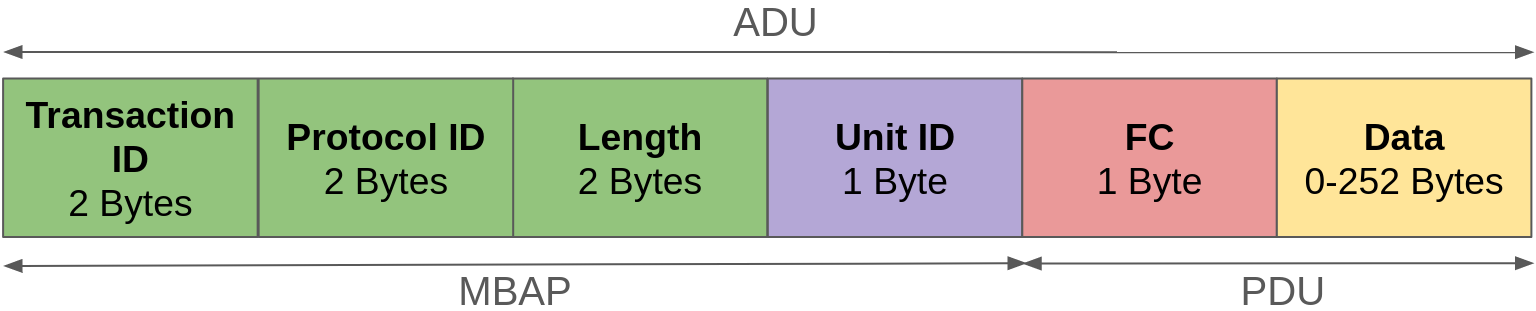
The Data field of the frame acts the same as with Modbus RTU, depending on the function code used.
There are no comments for now.
to be the first to leave a comment.