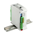
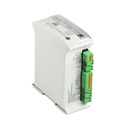
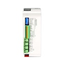
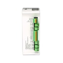
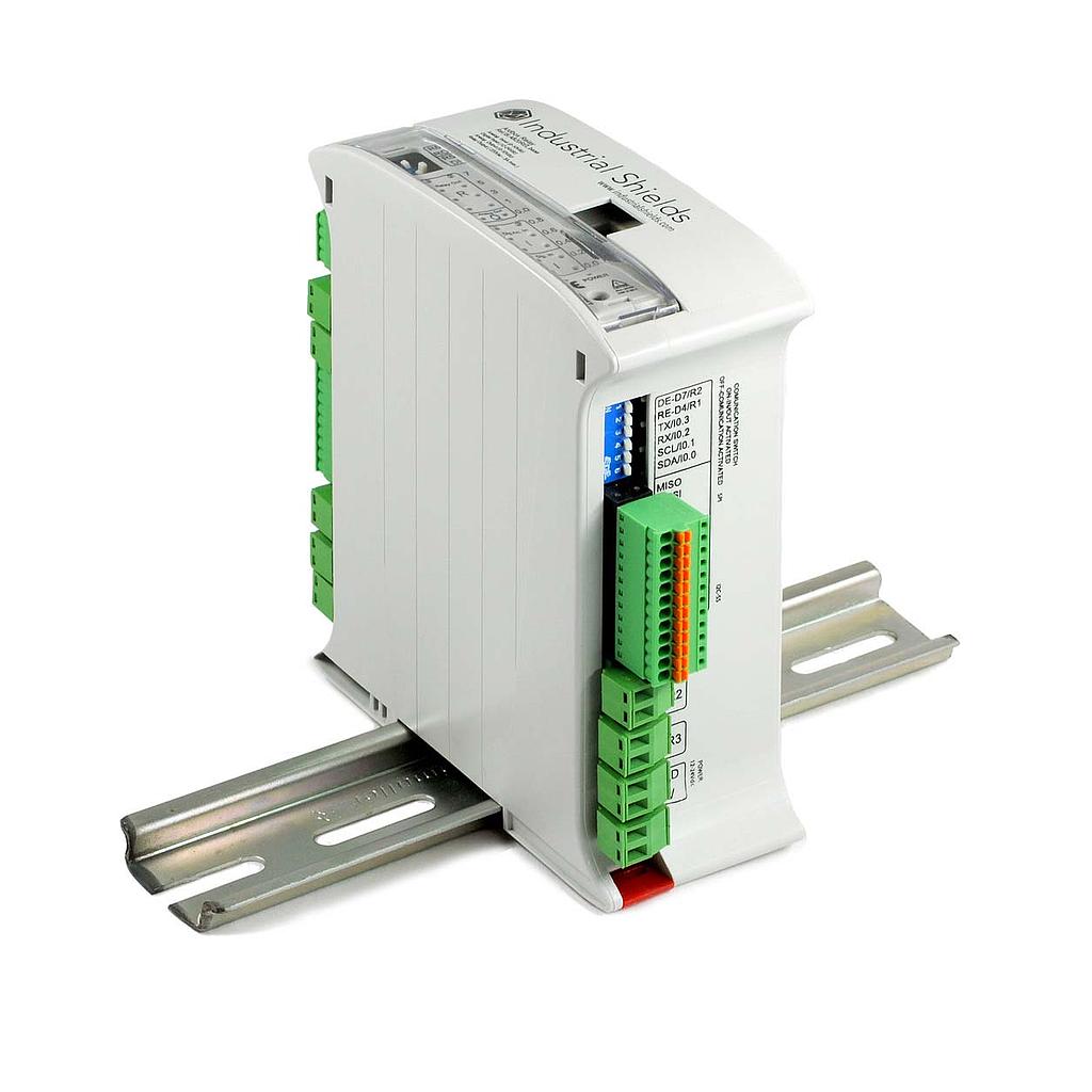
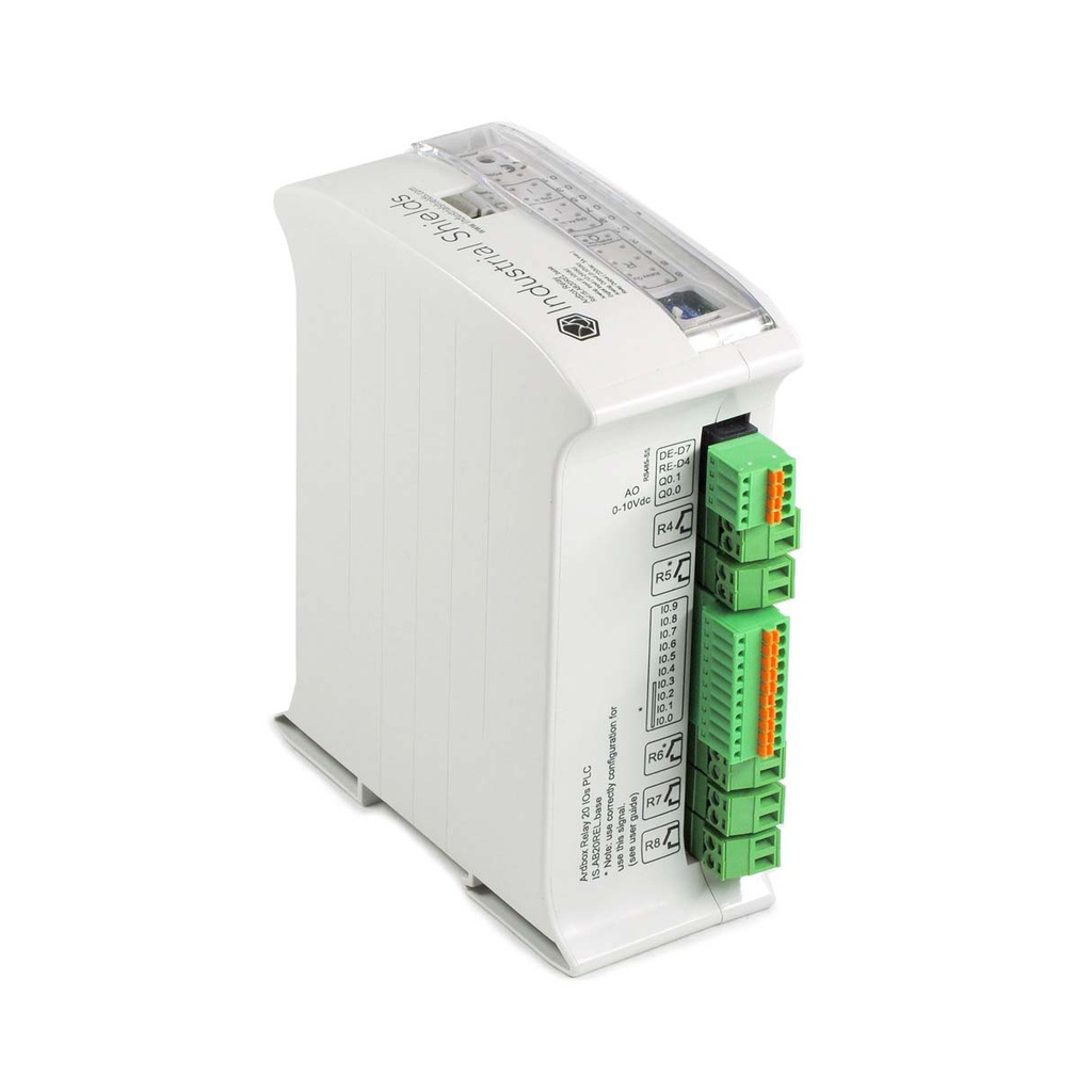
Arduino PLC Ardbox Relay: 20 I/Os with digital, analog and relay outputs
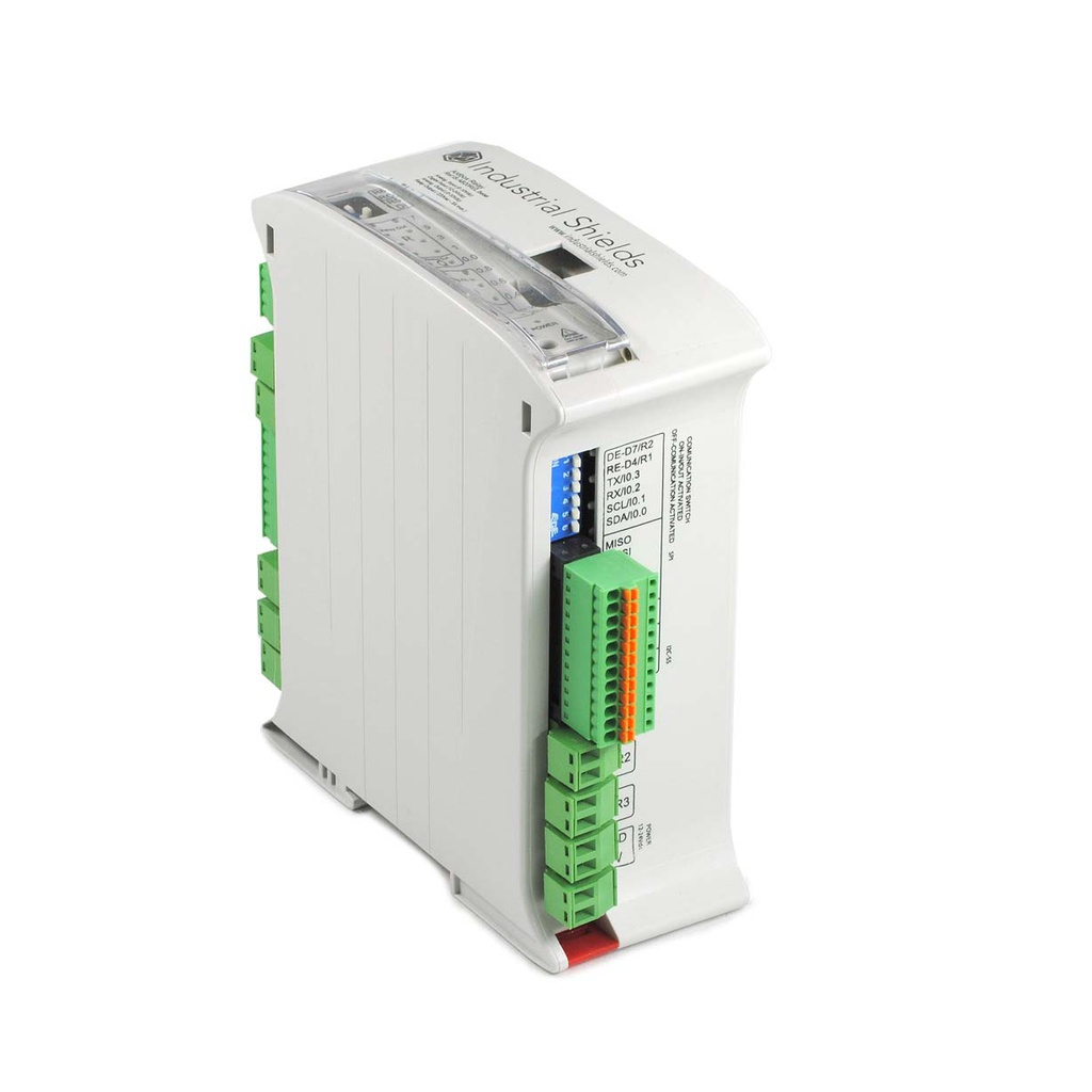
The Ardbox Relay is a compact industrial PLC based on the Arduino Leonardo. It offers 20 I/O points: 6 convertible analog/digital inputs (0 to 10 Vdc), 4 digital isolated inputs, one of them interrupt capable, 2 configurable digital/analog outputs and 8 relay outputs. It communicates over RS-485, RS-232, I2C and SPI, with no onboard Ethernet. It is built for small and medium automation projects where space is limited but reliability still matters.
Technical Specifications
| Specification | Value |
|---|---|
| Part Number | IS.AB20REL.HF+ |
| Total I/Os | 20 |
| Architecture | 1 layer (ArdboxRLayer) |
| Microcontroller | Arduino Leonardo |
| Inputs | 10 |
| Convertible Analog/Digital Inputs (0 to 10 Vdc) | 6 |
| Digital Isolated Inputs (5 to 24 Vdc) | 4 |
| Interrupt Capable Inputs | 1 |
| Outputs | 10 |
| Digital/Analog Outputs (0 to 10 Vdc) | 2 |
| Relay Outputs | 8 (220 Vac, 5 A) |
| PWM Output | Not available (Ardbox Analog only) |
| Ethernet | No |
| RS-485 Ports | 2 |
| RS-232 Ports | 1 |
| SPI | Yes |
| I2C | Yes |
| RTC | No |
| MicroSD Slot | No |
| Power Supply | 12 to 24 Vdc |
| Max Power Consumption | 3.57 W |
| Mounting | DIN rail |
| Certifications | CE, RoHS |
Applications: pump control, lighting and small automation
The Ardbox Relay is suited to projects that need to switch pumps, motors, lighting or other loads directly, without adding external relay modules. Typical uses include water pumping stations, small HVAC installations, lighting control and general purpose industrial automation.
Protocols: RS-485, RS-232, I2C and SPI
Communication runs over RS-485 (2 ports) and RS-232 (1 port), with I2C and SPI available for local peripherals. The board has no onboard Ethernet.
Programming: Arduino IDE with Industrial Shields libraries
Programmed via Arduino IDE with the industrialshields boards package. All I/Os are referenced by name (I0_x, Q0_x, A0_x, R1 to R8).
Initial installation
Arduino IDE
Arduino IDE is the Original platform to program Arduino boards. This cross-platform application is available on Windows, macOS and Linux and under the GNU General Public License. Arduino IDE supports C and C++ code structuring. Industrial Shields recommend using Arduino IDE to program Arduino Based PLC's, but any Arduino compatible software are compatible with Industrial Shields Controllers.
Apart from that, Industrial Shields bring the possibility to select your Arduino based PLC into your Arduino IDE and compile your sketches for the different PLC's.
Download the Arduino IDE:
Install Industrial Shields units to Arduino IDE:
Power supply
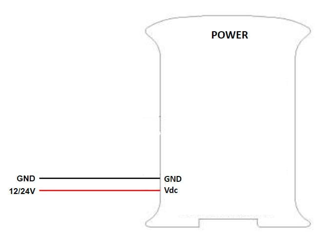
All Arduino based PLC's can be powered between 12-24V. Ardbox family, have a consumption between 700mA and 1500mA.
So, the recommended power supply is 2A or higher. Any Industrial power supply will be a good choice to power supply them.
REMEMBER:
Out units are designed to be powered between 12-24V. Just powering them with the USB, the unit will not be able to perform their features. USB is just to program the PLC's not to power them.
If, for some reason, you would like to use a power supply lower than 1.5A, contact Industrial Shields technical support to ensure that your system will complete your functionalities without any power issue.
Next is shown a simple diagram to see how to power supply any Industrial Shields unit.
Switch ARDBOX RELAY
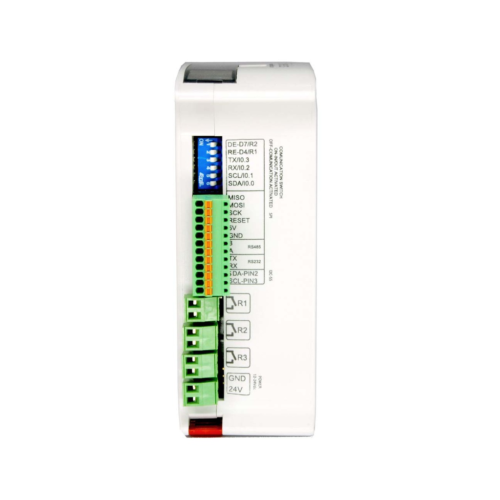
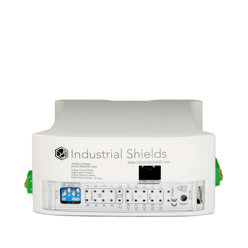
Ardbox Relay has two different switch areas:
TOP Zone:
SWITCH | ON | OFF |
1 - RS (RS485) | RS (RS485) | R8 |
2 - R8 | R8 | RS (RS485) |
3 - RS (RS485) | RS (RS485) | R7 |
4 - R7 | R7 | RS (RS485) |
RIGHT Zone:
SWITCH | ON | OFF |
1 - NC | - | - |
2 - HD-FD | HALF DUPLEX | FULL DUPLEX |
3 - R5/SCL | R5 | SCL |
4 - I0.0/SDA | I0.0 | SDA |
1 - RE-RS485 | RE-RS485 | I0.4 |
2 - I0.4 | I0.4 | RE-RS485 |
3 - DE-RS485 | DE-RS485 | I0.5 |
4 - I0.5 | I0.5 | DE-RS485 |
Power consumption
Ardbox relay:
Current (mA) | Power (W) | |
Idle | 31,83 | 0,76 |
Full workload | 149 | 3,57 |
Inputs & Outputs
Analog inputs
The analog inputs have a tolerance of 0 to 10 Vdc with 10 bits of resolution, they are also isolated and sharing the internal GND. In Digital and Analog I/O there's self insulation, so its posible to connect them in a different power supply than 24 Vdc.
Ardbox Relay - Inputs: 6 Analog (0-10Vdc) configurable by Software.
Digital inputs
Voltage variation from –Vcc (or GND) to +Vcc, with no intermediate values. Two states: 0 (-Vcc or GND) and 1 (+Vcc). In Digital and Analog I/O there's self insulation, so its posible to connect them in a different power supply than 24 V.
Ardbox Relay - Inputs: 4 Digital Isolated (5-24Vdc).
Interrupt inputs
Interrupt Service Rutine. A mechanism that allows a function to be associated with the occurance of a particular event. When the event occurs the processor exits immediately from the normal flow of the program and runs the associated ISR function ignoring any other task.
Ardbox Relay - Inputs: (1x) Interrupt Inputs (5-24Vdc). “Can work like Digital Input (24Vdc)”.
| Ardbox Pin | Arduino Leornardo Pin | Switch |
| I0.0 (INT1) | 2 | SDA/I0.0 at ON Position |
In this example we activate INT0 using pin I0_0.
Analog outputs
Voltage variation between –Vcc (or GND) and +Vcc, can take any value. An analog input provides a coded measurement in the form of a digital value with an N-bit number. In Digital and Analog I/O there's self insulation, so its posible to connect them in a different power supply than 24 V.
Ardbox Relay - Outputs: 2 Analog 0-10V output, configurable by switch.
Digital outputs
Voltage variation from –Vcc (or GND) to +Vcc, with no intermediate values. Two states: 0 (-Vcc or GND) and 1 (+Vcc). In Digital and Analog I/O there's self insulation, so its posible to connect them in a different power supply than 24 V.
Ardbox Relay - Outputs: 2 Digitals (5 to 24Vdc). The Ardbox Relay does not provide PWM output; this feature is only available on the Ardbox Analog model.
Relays
A relay is an electromagnetic switch controlled by an electric signal. In Industrial Shields units these devices are already integrated in their boards and can be accessible directly with the function digitalWrite(RX, HIGH). Industrial Shields relays are normally open and can handle a max current of 4A for max voltage 230Vac and 2A for a max DC voltage of 24Vdc.
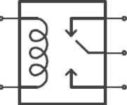
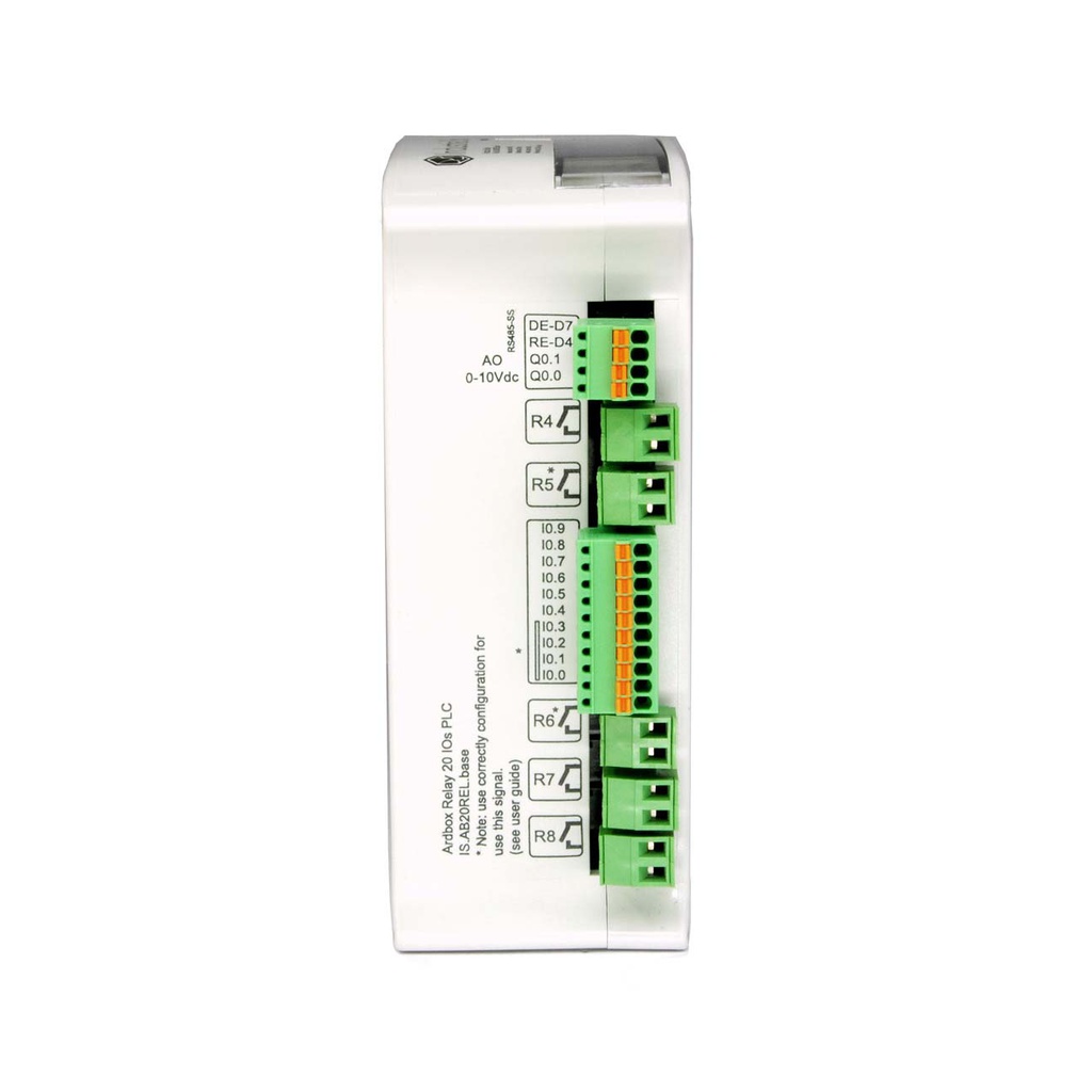
Ardbox Relay - Outputs: 8 Relay outputs (220Vac – 5A). (R1, .. , R8)
Communications
RS-485
RS-485, also known as TIA-485(-A), EIA-485, is a standard defining the electrical characteristics of drivers and receivers for use in serial communications systems. The electrical signaling is balanced, and multi-point systems are supported.
Make sure you have your switches and jumpers configured properly before using this serial communication.
Example of use
Basic RS-485 write example (send):
Basic RS-485 read example (receive):
Basic RS-485 full-duplex example:
* Remember that to test the full duplex with your Ethernet PLC you must connect the A, B (receivers) to the Y, X(transmitters).
RS-232
RS-232, also known as TIA-232-F, EIA-232-F, or V.24, is a standard for serial communication transmission of data. It specifies the voltage levels, signal timing, and data protocol for communication between devices.
Make sure you have your switches and jumpers configured properly before using this serial communication.
Example of use
Basic RS-232 write example
Basic RS-232 read example
I2C
I2C is a synchronous protocol that only uses 3 cables, one for the clock (SCL) and one for the data (SDA) and ground (GND). This means that the master and the slave send data through the same cable, which is controlled by the master, who creates the clock signal. I2C uses addressing to select slaves.
I2C is a serial communications bus. The speed is 100 kbit/s in standard mode, but also allows speeds of 3.4 Mbit/s. It is a very used bus in the industry, mainly to communicate microcontrollers and their peripherals in integrated systems, or to communicate integrated circuits that reside in a same PCB.
Make sure you have your switches and jumpers configured properly before using this serial communication.
Example of use
IMPORTANT: Make sure to download the Arduino based PLC boards for Arduino IDE.
Simple example of scanning I2C:
SPI
SPI is a synchronous communication protocol bus that has a master-slave architecture. Slave devices cannot initiate communication, nor exchange data with each other directly. Only the master can select to which slave will communicate with through the SS (slave select) pin.
Example of use
Extra features
Direct Arduino Pins
If we want to use another Serial Port using your equipment, we can make use of some digital pins to create a Serial. The SoftwareSerial library has been developed to allow serial communication on other digital pins of the Arduino, using software to replicate the functionality. It is possible to have multiple software serial ports with speeds up to 115200 bps. A parameter enables inverted signaling for devices which require that protocol.
Only I/O 5V from Ardbox or M-Duino boards can be used.
| M-Duino Pins | Leonardo Pins |
| MISO | 14 |
| MOSI | 16 |
| SCK | 15 |
5VDC Signals
These pins can be programmed according to Arduino features such as I/Os operating at 5V or any additional features present in the pins.
I2C Pins – SDA/SCL:
The I2C protocol is meant to work in a pull-up configuration. In this case it reads 5V when nothing is connected.
SPI – MISO/MOSI/SCK:
These pins can only work as a 5V pins if the Ethernet protocol is not going to be used. As the Ethernet protocol uses the SPI to communicate with the Arduino board, both behaviours cannot happen at the same time as the Ethernet would not work.
Pin2/Pin3:
These pins are only referred to the inputs I0.5/I0.6. If the switch configuration is in OFF position the pins Pin 2/Pin 3 will be available.