Complete guide: OpenPLC with industrial PLCs
To program an ESP32 PLC, M-Duino or Ardbox from OpenPLC, install the Industrial Shields mod in the OpenPLC Editor folder and select your PLC model as the board in Transfer Program to PLC. The IEC addresses follow the names printed on the PLC: %IX1.4 is input I1_4 and %QX0.5 is output Q0_5. Analog signals use one index (%IW, %QW), outputs that can be analog or digital start as analog, and C++ code with the Industrial Shields libraries goes in an Arduino extension.
This guide covers the installation of the mod, the default I/O mapping, how to switch an analog output to digital in a normal zone and in a relay zone, and a first Arduino extension. The examples use an M-Duino 42+, and the I/O Config screenshots an M-Duino 58+ and an M-Duino 57R+. The steps are the same on any M-Duino PLC, Ardbox or ESP32 PLC if you select the right model.
The Industrial Shields mod was published in 2024 for the OpenPLC Editor of that time, and the screenshots come from that editor. OpenPLC Editor v4 is a new application: before you start a project, check that your model appears in its board list, or ask us.
Which Industrial Shields PLCs you can program with OpenPLC
| Family | Based on | In OpenPLC |
|---|---|---|
| M-Duino | Arduino Mega | Selectable board with the mod. Relays are digital outputs |
| Ardbox | Arduino Leonardo | Selectable board with the mod |
| ESP32 PLC, including the ESP32 PLC 14 | ESP32 | Selectable board with the mod |
| Raspberry PLC | Raspberry Pi | No OpenPLC I/O mapping from Industrial Shields. Use CODESYS for IEC 61131-3 |
If you are not sure which family fits your project, read how to choose an industrial controller.
Install the Industrial Shields mod in OpenPLC
- Install the OpenPLC Editor and open it at least once. If you have just updated it, open it once too, because an update overwrites the changes of the mod.
- Close the editor and download the mod, a Windows installer: ISModInstaller.exe.
- Run it. When it asks for the install folder, select the OpenPLC Editor folder, usually in your user folder.
- Open the editor, go to Transfer Program to PLC and check that your PLC model is in the board list.
After each update of the OpenPLC Editor, install the mod again.
How the inputs and outputs are addressed
OpenPLC uses IEC 61131-3 addresses: digital signals have two indexes and analog signals have one. The mod maps the PLC like this by default:
| Signal | IEC address | Default mapping | Example (M-Duino 58+) |
|---|---|---|---|
| Digital inputs | %IX | Same indexes as the PLC. Pins named 99 fill the gaps and OpenPLC ignores them | I1_4 is %IX1.4 |
| Digital outputs and relays | %QX | Same indexes as the PLC, with the same padding. Relays are digital outputs | Q0_3 is %QX0.3 |
| Analog inputs | %IW | One index, in the order of the list, no padding | I0_7 is %IW0, I0_8 is %IW1 |
| Analog outputs | %QW | One index, no padding. Outputs that can be analog or digital start as analog | A0_5 is %QW0 |
To see the exact map of your model, open Transfer Program to PLC, select the board and go to I/O Config. Each list position is one address: in the digital lists, position n is index n / 8 and bit n mod 8, counting from 0. OpenPLC handles analog values from 0 to 65535; the scaling for each family is in the external variables guide.
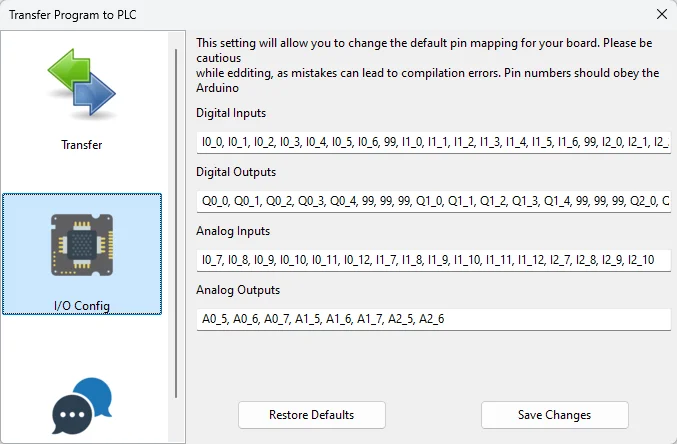
Switch an analog output to digital
Outputs such as A0_5 / Q0_5 can work as analog or digital. OpenPLC starts them as analog. To use one as digital, change two things in I/O Config and the physical switch of the PLC.
In a normal zone
Example: output A0_5 of the first zone of an M-Duino 58+.
- In Analog Outputs, replace
A0_5with99. - In Digital Outputs, replace the first
99withQ0_5. - Click Save Changes.
The output keeps an address that matches its name: %QX0.5 is Q0_5.
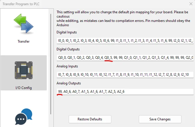
In a relay zone
Example: output A0_0 of the first relay zone of an M-Duino 57R+. The relays already fill the first digital output indexes, so the output goes to the end of the list.
- In Analog Outputs, replace
A0_0with99. - Add
Q0_0at the end of Digital Outputs. - Click Save Changes.
Here the address does not match the name: Q0_0 becomes %QX3.0. Write it down in the comment of the variable.
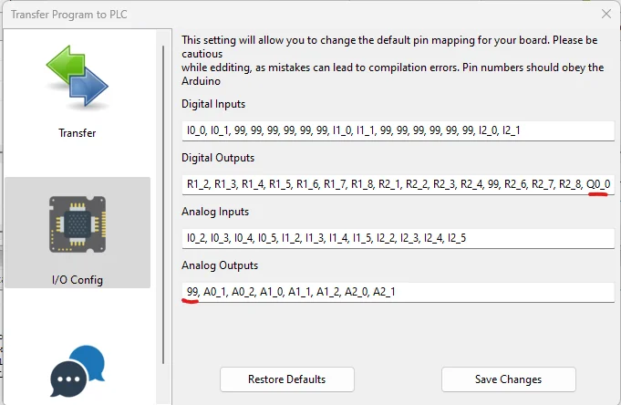
Set the switch on the PLC
Each switchable output has a switch on the PLC: ON is digital, OFF is analog. The software and the switch must agree. Restore Defaults in I/O Config brings back the original map.
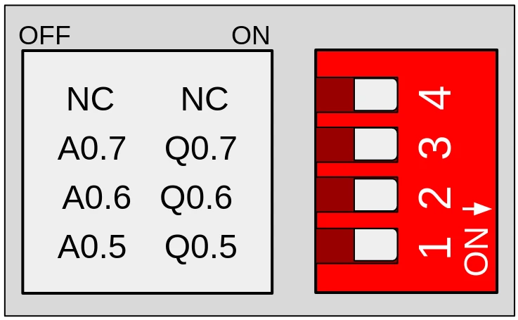
Add C++ code with an Arduino extension
The mod builds the ESP32 PLC, M-Duino and Ardbox boards with the Industrial Shields libraries, so an Arduino extension can use the same pin names and functions as a sketch in the Arduino IDE. Use it for what Ladder cannot do, such as a protocol or a library. Keep the OpenPLC Editor up to date to have Arduino extensions.
With a project open, click the grey plus icon and select Arduino extension.
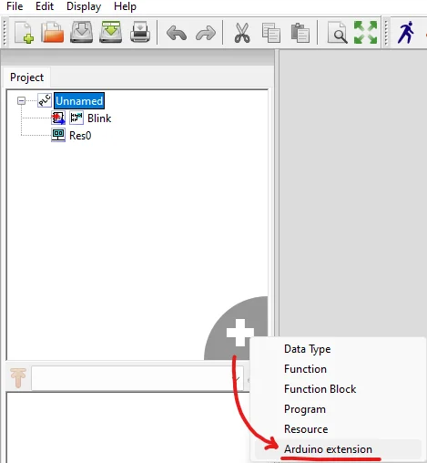
sketch_setup() runs once at start, and sketch_loop() runs once per PLC scan, after the Ladder program. This example blinks Q0_0 every 500 ms:
// Arduino extension: toggles Q0_0 every 500 ms without stopping the PLC scan
unsigned long lastToggle = 0;
bool q0State = false;

void sketch_setup()
{
    pinMode(Q0_0, OUTPUT);
}

void sketch_loop()
{
    if (millis() - lastToggle >= 500)
    {
        lastToggle += 500;
        q0State = !q0State;
        digitalWrite(Q0_0, q0State ? HIGH : LOW);
    }
}
It compiles for an M-Duino 21+ with the Industrial Shields AVR boards 1.2.1. Two rules avoid most problems:
- Do not use
delay().sketch_loop()runs inside the scan, so a delay stops the Ladder program and Modbus for that time. Count time withmillis(), as above. - Drive from C++ only outputs that the Ladder program does not use. OpenPLC writes the outputs that have an IEC variable on every scan. With Modbus enabled, it writes every output in I/O Config, so replace the output with 99 there first.
To share variables between the Ladder diagram and the extension, continue with Creating external variables in OpenPLC to interact with an Arduino extension.
FAQ about OpenPLC on Industrial Shields PLCs
Do I need the mod to use an M-Duino in OpenPLC?
The mod adds the Industrial Shields boards and their I/O map. Before it existed, you could select the Arduino Mega and map the pins by hand, as in Mapping any M-Duino PLC for OpenPLC. With the mod, the addresses follow the PLC names.
Why is %IX1.4 the input I1_4?
The mod fills the gaps between zones with padding pins (99), so the two indexes of the IEC address are the zone and the input number of the PLC.
Why is my output analog when I want it digital?
Switchable outputs start as analog. Move them to Digital Outputs in I/O Config and set the switch on the PLC to ON.
Can I use Modbus with these PLCs in OpenPLC?
Yes, from the Communications tab of Transfer Program to PLC. Using Modbus on Arduino Mega with OpenPLC shows how IEC addresses become coils and registers.
Can I still program the PLC in the Arduino IDE?
Yes. Uploading from the Arduino IDE replaces the OpenPLC program, and the other way round. See how to install the Industrial Shields boards in the Arduino IDE.
Other OpenPLC guides
Take it further
OpenPLC runs IEC 61131-3 programs. See sequences of the same kind at work: a GRAFCET bench, a start sequence simulator and a state machine in code.
Case study
Prove a pneumatic sequence on a bench first.
A belt, 3 cylinders, 8 sensors and one Arduino based PLC, programmed as 8 GRAFCET steps.
Read the case study
Simulator
Start a turbine or a pump step by step, and stop it safely
A Raspberry PLC 42 runs the start as a state machine and reads 4-20 mA transmitters for level, flow, vibration and pressure.
Open the simulator
PLC Solution Library
Safe solenoid valve sequencing on an ESP32 PLC with a state machine
Every actuation goes through one state machine, so a mixed load and unload condition cannot exist in the firmware.
See the example