Complete guide: OpenPLC with industrial PLCs
To program an Arduino Mega with OpenPLC, install the OpenPLC Editor, open the Blink example and give each variable the IEC address of the pin you want to use. The built-in LED is on PWM pin 13, which OpenPLC maps as the analog output %QW11, so you drive it with a UINT variable and two MOVE blocks that write 65535 (on) or 0 (off). Simulate the program in the Editor, then select Arduino Mega and the COM port and click Transfer to PLC.
OpenPLC is open source PLC software. You write the program in IEC 61131-3 languages such as Ladder Diagram or Structured Text, and the Editor compiles it into firmware for the board, so you do not write any C++. This is the first guide of the series. If you want to know what OpenPLC is and when it makes sense, start with the OpenPLC guide for industrial PLCs.
Which Editor version? The screenshots come from the classic OpenPLC Editor, the Python application. OpenPLC Editor v4 is a new application with a different interface, so its menus and buttons look different. The Ladder program and the IEC addresses are the same idea in both; check the board list and the pin mapping in the Editor you install.
What you need
- An Arduino Mega 2560 and its USB cable (type B).
- The OpenPLC Editor, from the official site, autonomylogic.com. The first time you open it, it takes a while to load.
- Nothing else. The Editor carries its own Arduino command line tools and installs the board core the first time you transfer a program, so you do not need the Arduino IDE.
For this first test you only need the Editor. The OpenPLC Runtime is for Linux computers; on an Arduino board the Editor uploads the program as firmware and the board itself becomes the PLC.
How OpenPLC maps the Arduino Mega pins
OpenPLC names every input and output with an IEC 61131-3 address instead of a pin number. %I is an input, %Q an output, X a single bit (BOOL) and W a 16-bit word, which OpenPLC uses for analog values from 0 to 65535. Digital addresses have two indexes (%QX1.0), analog addresses one (%QW11). This is the default map of the Arduino Mega in the OpenPLC Editor board definitions:
| Signal | IEC addresses | Arduino Mega pins, in order |
|---|---|---|
| Digital inputs | %IX0.0 to %IX2.7 | 62 to 69 (A8 to A15), then 22, 24, 26 ... 52 |
| Digital outputs | %QX0.0 to %QX2.7 | 14 to 21, then 23, 25, 27 ... 53 |
| Analog inputs | %IW0 to %IW7 | A0 to A7 |
| Analog (PWM) outputs | %QW0 to %QW11 | 2 to 13 |
Pin 13, the one with the built-in LED, is the last PWM output, so its address is %QW11. It is not in the digital output list, which is why you cannot simply give it to the BOOL variable of the Blink example. The exact map of your board is in the I/O Config section of the Transfer Program to PLC window.
Step 1: open the Blink example
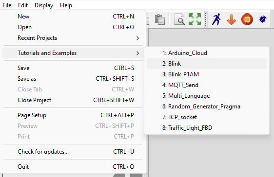
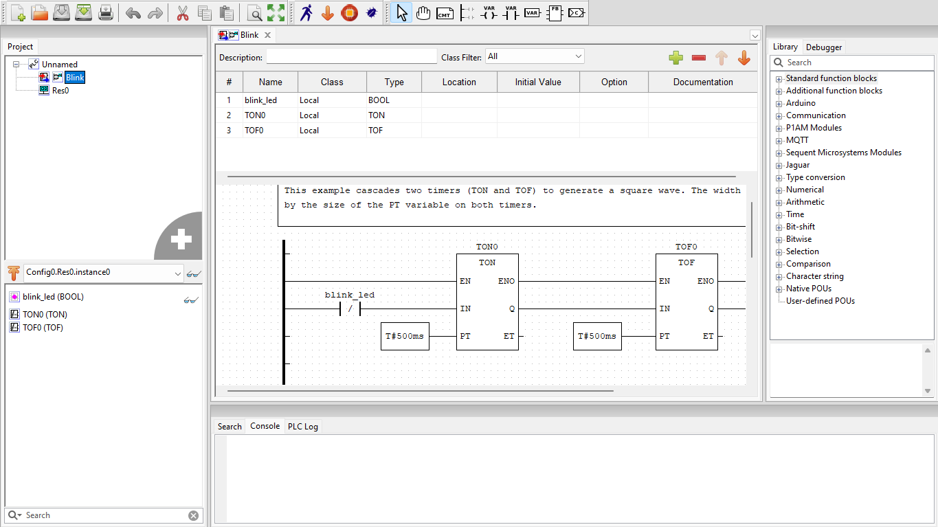
Open the OpenPLC Editor and go to File, Tutorials and Examples, Blink. We use it as a template: it toggles a BOOL variable, blink_led, every 500 ms with two timers.
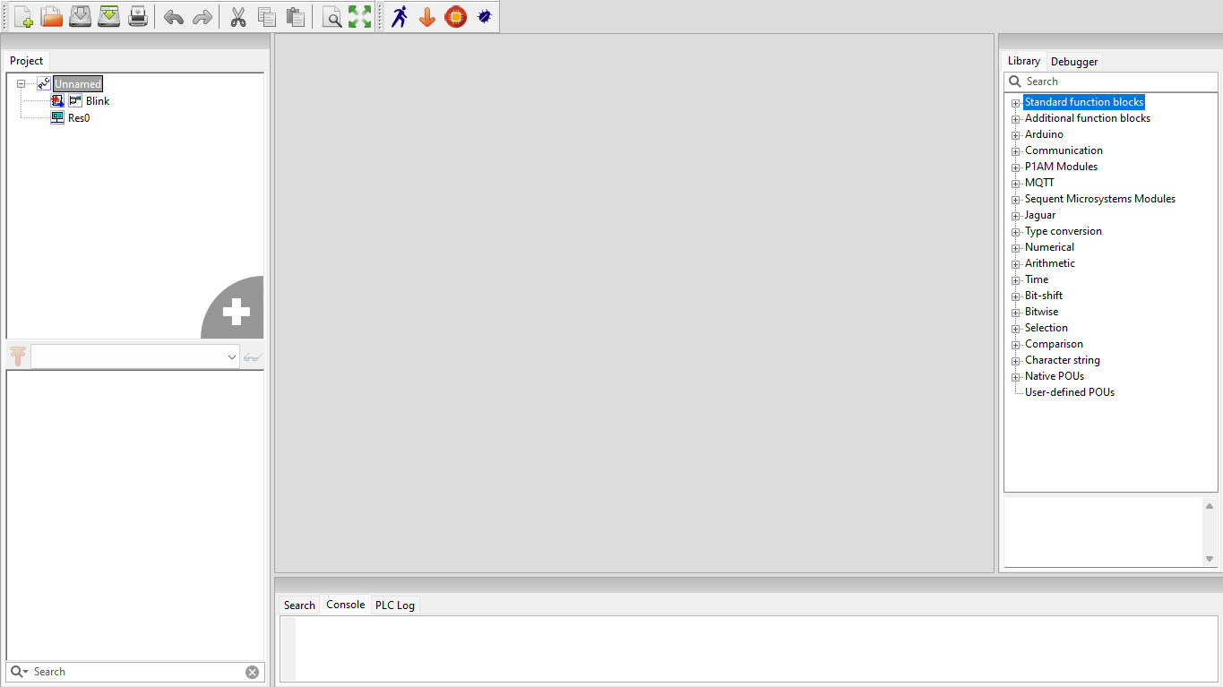
At first the editor area is empty.
Double click Blink in the Project tree (top left). The variables table appears at the top and the Ladder diagram below it. If the side panels hide the diagram, press F12 to enlarge it and F12 again to go back.
blink_led.Step 2: declare the LED output
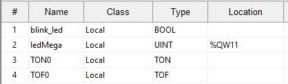
Add a variable with the green + button of the variables table. Double click its cells to name it ledMega, set the type to UINT and the location to %QW11. UINT is a 16-bit unsigned integer, the type that fits a word address.
Step 3: write 65535 or 0 with MOVE blocks
The next steps use two tools of the Ladder toolbar, marked in red: the variable tool and the block tool.

- Select the block tool and click under
blink_led. Search for the MOVE block, tick Execution control and place it. Connect the EN input of MOVE to the Q output of TOF0, and its ENO output to the right power rail.
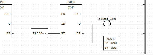
- Select the variable tool and click to the right of MOVE. Choose the class Output and the expression
ledMega, and connect it to OUT. Then add another variable to the left of MOVE with the class Input and the expression 65535, and connect it to IN.
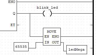
When EN is TRUE, MOVE copies IN to OUT, so ledMega receives 65535 while blink_led is on. 65535 is the top of the OpenPLC analog range and 0 the bottom. On the Arduino Mega, OpenPLC divides the value by 256 before it calls analogWrite(), so 65535 becomes a PWM duty of 255 (fully on) and 0 turns the pin off.
- Repeat the same structure before TON0, after the negated
blink_ledcontact, and write 0 instead of 65535. This MOVE sends 0 toledMegawhileblink_ledis off.
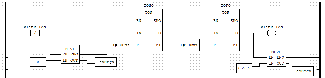
ledMega while blink_led is off, 65535 while it is on.Step 4: simulate the program
Test the logic before you connect the board. Click the blue running figure to start the PLC simulation.
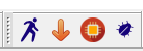
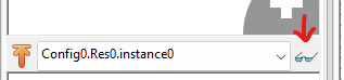
Then click the glasses next to the instance (Config0.Res0.instance0) to debug it.
The Ladder diagram now shows active signals in green and values in purple. To follow one variable, click its glasses icon in the list.
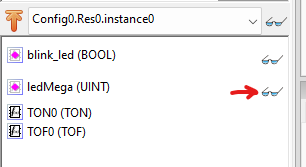
ledMega should change between 0 and 65535 every half second. Stop the simulation with the red STOP button.
Step 5: transfer the program to the Arduino Mega
Connect the Arduino Mega to the computer and click the orange processor button.

In Board Type select Arduino Mega, select the COM port of the board and click Transfer to PLC. The Editor compiles the program and uploads it. If the board shows [NOT INSTALLED], the Editor installs the board core first, so the first transfer takes longer. When it finishes you will see Done! in the compilation output.
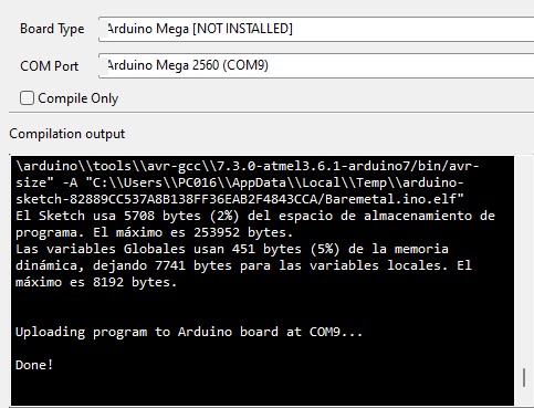
The built-in LED now blinks every half second. The program runs from the board's flash memory, so it keeps running without the computer.
If the LED does not blink
| What you see | Likely cause | What to do |
|---|---|---|
ledMega stays at 0 in the simulation | MOVE has no execution control, or EN is not connected to the timer output | Place MOVE again with Execution control ticked and connect EN to Q of TOF0 |
| The LED never lights | The location is a digital address such as %QX | Pin 13 is only mapped as %QW11: use a UINT variable at that address |
| The LED stays on | The MOVE that writes 0 is missing | Add the second MOVE after the negated blink_led contact |
| The upload fails | Wrong COM port, or another program is using the port | Close any serial monitor and pick the port that appears when you plug in the board |
From an Arduino Mega to an industrial PLC
An Arduino Mega is a good board to learn OpenPLC, but its pins work at 5 V and it has no protection for the wiring of a machine. The M-Duino family is based on the Arduino Mega and runs the same kind of OpenPLC program with 24 V inputs and outputs, relays and DIN rail mounting. With the Industrial Shields mod for the Editor you select your M-Duino, Ardbox or ESP32 PLC model as the board, and the addresses follow the names printed on the PLC (%IX1.4 is I1_4). The steps are in Using ESP32 PLC, M-Duino and Ardbox with OpenPLC. To compare controller types first, read how to choose an industrial controller.
See a PLC sequence at work on an M-Duino. In the end-of-line test simulator, an M-Duino 42 runs continuity, insulation and functional test steps and marks each one OK or KO. Inject a fault and see which step stops the test.
Open the end-of-line test simulatorRead the pneumatic test bench case
FAQ about OpenPLC and Arduino Mega
Do I need the OpenPLC Runtime for an Arduino?
No. The Runtime runs programs on Linux computers. For an Arduino board the Editor compiles the program and uploads it as firmware, and the board runs it on its own.
Why is the built-in LED an analog output?
Because OpenPLC maps pins 2 to 13 of the Mega as PWM outputs, %QW0 to %QW11. Pin 13 is not in the digital output list, so it only accepts a 16-bit value.
Can I use Structured Text instead of Ladder?
Yes. The Editor supports the IEC 61131-3 languages: Ladder Diagram, Structured Text, Function Block Diagram, Instruction List and Sequential Function Chart. The IEC addresses work the same in all of them.
Which other Arduino boards work with OpenPLC?
The Editor board list includes, among others, the Arduino Uno, Leonardo, Nano, Due, Mega and several ESP32 and Raspberry Pi Pico boards. Each one has its own pin map, which you can see in I/O Config.
Does the simulation use the real board?
No. The simulation runs the program on the computer, without inputs or outputs. Use it to check the logic, then transfer the program to test the hardware.
Can the Arduino Mega talk Modbus with OpenPLC?
Yes. Enable Modbus in the Communications tab of the transfer window and the board becomes a Modbus slave. The next guide, Using Modbus on Arduino Mega with OpenPLC, shows how.
Next steps in the OpenPLC series
- Using Modbus on Arduino Mega with OpenPLC
- Using ESP32 PLC, M-Duino and Ardbox with OpenPLC
- External variables between Ladder and an Arduino extension
- Live debugging with OpenPLC
All the guides, compatibility by PLC family and the FAQ are in the OpenPLC guide for industrial PLCs. Questions about your project? Ask an engineer.