Case study · Vehicle tracking · M-Duino
Every truck reports. Headquarters can answer.
GPS, GPRS and Bluetooth on one Arduino based PLC per truck, on 12 V.
Position goes up to the server.
Messages come back to the driver phone.
This case describes a fleet management system with an Arduino based PLC of Industrial Shields in each vehicle. It does not name the customer. This page is about the architecture: how the data goes from each truck to a server and to the screens at headquarters, and how a message goes back to the driver. Two other pages show a separate case study, a frozen food fleet: one about route efficiency and one about the cold chain.
The challenge
See every truck. Reach every driver.
The goal: install in each vehicle of the fleet the same Arduino based equipment, with its set of sensors and actuators. It must get the location, direction and speed of each vehicle, send them to a server with its database, show them on screen at headquarters, and let headquarters send a message to the desired truck.
Where is each truck
Location, direction and speed of every vehicle, from a GPS module on board.
Data on a server
The data goes to a server and is stored in a database, so headquarters can reach it from the cloud.
Messages to the driver
Headquarters sends an alert or a message to the desired truck. The driver gets it on the mobile phone.
A fleet that changes
New trucks join the fleet. They must not affect the correct operation of the fleet management system.
One PLC, three modules
Each truck carries an Arduino based PLC on the 12 V supply of the truck, with a GPS module, a GPRS module with a SIM card and a BT/LE module.
How it works
Three loops: report, message, scale.
Each loop shows one data path of the system. Press the buttons. The panels are illustrative simulations: record rates, message texts, truck numbers and loads are examples, not data from the fleet.
GPS to the PLC, GPRS to the server, server to the screen.
The GPS module gives the location, direction and speed of the vehicle. The GPRS module, connected to a SIM card, sends the data to the cloud. The server collects it and stores it in the database, then sends it to the terminals at headquarters, which show it in a visual graphic interface. Press the button to follow one record.
- GPS module: location, direction and speed
- GPRS module with a SIM card: data to the cloud
- Server and database, screens at headquarters
Illustrative simulation. Example values, no data from the fleet. Example: one record with the position, the direction and the speed every 30 seconds while the truck moves.
From the screen at headquarters to the phone in the cab.
In the terminals, the same interface sends alert messages to the desired truck. The message travels over GPRS to the Arduino based equipment. The BT/LE module passes it on, and the mobile phone of the driver receives it instantly. On the phone, an app receives the message over Bluetooth LE; the case does not publish the app. Pick a truck and send a message. A typical design choice: keep the message on the PLC if the phone is not connected.
- Alert messages to the desired truck
- GPRS to the PLC, Bluetooth LE to the phone
- The driver phone gets the message instantly
Message path (example)
Illustrative simulation. Example values, no data from the fleet. Example behaviour: if the phone is not connected, the PLC keeps the message and sends it when the phone is back.
New trucks join the fleet without breaking it.
The system is scalable. It is designed so that new trucks can join the fleet without affecting the correct operation of the fleet management system. A typical way to do it: each unit sends its own ID with every record, and the server accepts a new unit once it is registered. Add trucks and watch the load on the server.
- Same equipment in every truck
- New trucks do not affect the others
- One server and one database for the whole fleet
Illustrative simulation. Example values, no data from the fleet. Example: one record every 30 seconds per truck. Each new unit gets its own ID and SIM card and joins without changes to the others.
Server side example: a Node-RED MQTT concentrator for PLC fleets
System architecture
How does a GPS GPRS vehicle tracking system with an Arduino PLC work?
In each truck, an Arduino based PLC on the 12 V supply reads a GPS module and talks to a GPRS module and a BT/LE module over serial lines (Rx and Tx in the scheme of the case). The GPRS module sends the data to the cloud, where servers store it in a database and send it to the screens at headquarters. Messages from headquarters take the same path back, and the BT/LE module passes them to the driver phone.
| Signal | Between | Type | Purpose |
|---|---|---|---|
| Position data | BetweenGPS module → PLC | TypeSerial (Rx, Tx) | PurposeLocation, direction and speed of the vehicle |
| Fleet data | BetweenPLC → GPRS module → cloud | TypeGPRS, SIM card | PurposeInformation data and driver messages to the server |
| Storage | BetweenServers → database | TypeDatabase | PurposeEvery record of every truck |
| Display | BetweenServers → terminals at headquarters | TypeVisual interface | PurposeThe fleet on screen |
| Alerts and messages | BetweenHeadquarters → cloud → GPRS module → PLC | TypeGPRS | PurposeA message to the desired truck |
| To the driver | BetweenPLC → BT/LE module → driver phone | TypeBluetooth LE | PurposeThe driver phone gets the message instantly |
| Power | BetweenTruck → PLC | Type12 V DC | PurposeThe PLC runs on the truck supply. The scheme shows 5 V to the GPRS module |
Why it works
One controller per truck, two ways to talk.
Same equipment everywhere
Every truck gets the same Arduino based PLC and the same three modules. One program, one way to install it.
Two-way link
The GPRS module sends the data up and brings the messages down. Headquarters can see and can answer.
The phone the driver already carries
The BT/LE module sends the message to the mobile phone of the driver. The case uses the phone instead of a screen in the cab.
Built to grow
The system is designed so that new trucks join without affecting the fleet management system.
Modules you can change
GPS, GPRS and BT/LE are separate modules on serial lines. If the mobile network changes, the modem can change with it.
A program you own
The PLC is programmed with the Arduino IDE. You can read the program, change it and add a sensor.
Hardware used
An M-Duino on every truck.
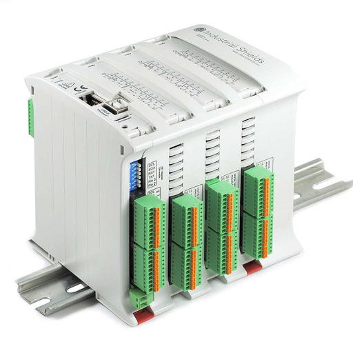
M-DUINO ETHERNET PLC ARDUINO 58
An industrial PLC built on an original Arduino Mega 2560, with 36 inputs and 22 outputs, Ethernet, RS-485, RS-232, a real-time clock and a microSD slot, for DIN rail. The M-Duino family has GPRS/GSM versions. In this case the PLC of each truck reads the GPS module and talks to the GPRS and BT/LE modules.
- Role
- GPS reading, GPRS link, messages to the BT/LE module
- Inputs
- 36: 16 analog/digital (0‑10 V), 20 digital optoisolated
- Outputs
- 22: 8 analog/digital/PWM (0‑10 V), 14 digital optoisolated
- Comms
- Ethernet, RS‑485, RS‑232, TTL serial, I2C, SPI. GPRS/GSM version in the family
- Built in
- Real-time clock, microSD slot
- Power supply
- 12 to 24 Vdc
The case says "an Arduino based PLC" and does not publish the model. The scheme of the case draws an M-Duino, and the original case material shows the M-Duino 58. The image and the link show the M-DUINO ETHERNET PLC ARDUINO 58.
Questions about this case
How does a GPS GPRS vehicle tracking system work?
A GPS module in the vehicle gives the location, direction and speed. A controller reads it and a GPRS modem with a SIM card sends the data over the mobile network to a server. The server stores it in a database and shows it on screens at headquarters. In this case, each truck has an Arduino based PLC on the 12 V supply with a GPS module, a GPRS module and a BT/LE module.
How does headquarters send a message to a truck driver?
In this case, the same interface that shows the fleet sends an alert message to the desired truck. The message goes over GPRS to the PLC of that truck, and the BT/LE module passes it to the mobile phone of the driver, who receives it instantly. On the phone, an app receives the message over Bluetooth LE. The case does not publish the app. Read how to connect a Bluetooth module to an Arduino based PLC.
How are the GPS, GPRS and Bluetooth modules connected to the PLC?
The scheme of the case shows each module on Rx and Tx lines to the PLC, and 5 V to the GPRS module. Most GPS modules send NMEA sentences over serial, and GPRS and BLE modules take AT commands. See GPS shields using Arduino and testing a GPRS module with an Arduino based PLC.
Is GPRS still a good choice for a new tracking project?
It depends on the country. Many operators have switched off or plan to switch off their 2G networks, which carry GPRS. For a new project, check the coverage on your routes and consider LTE-M or NB-IoT. The architecture stays the same: only the modem changes. For example, an ESP32 PLC 21 FLEX takes a 4G LTE-M/NB-IoT board and has Bluetooth LE built in, so the BT/LE module is not needed. Read GPRS and Narrowband with the ESP32 PLC family. For a newer build with 4G LTE-M, see the railway carriage case.
Is it safe to send messages to a driver who is driving?
The case sends messages to the driver phone and does not publish how the driver reads them. Rules on phone use while driving depend on the country. A safe design shows the message hands-free or only when the vehicle is stopped, and keeps alerts short.
Which parts of this case are facts, and which are examples?
Facts: an Arduino based PLC of Industrial Shields in each truck, on the 12 V supply; three modules (GPS, GPRS with a SIM card, BT/LE); location, direction and speed sent to a server and a database; screens at headquarters with a visual interface; alert messages to the desired truck, delivered to the driver phone through Bluetooth; a scalable system. Examples: the record rate, the message texts, the behaviour when the phone is not connected, the truck count and the server load.
Download the case study
4-page PDF with the challenge, the logic, the architecture and the hardware. No form required.
Fleet management cases
Three pages, three angles.
Each page answers a different question. Read the one that matches your project, or all three.
What the GPS data says about routes
Food distribution fleet. Speeds, stops and routes on two very different test routes, and arrivals at large logistics centres.
Read the route caseCold chainGoods temperature and position on one unit
Same fleet, other angle. One standard Ardbox unit per truck: GPS, goods temperature, local data and GPRS to the data centre.
Read the cold chain caseGPS, GPRS and Bluetooth on one PLC
A separate case study. How data goes from each truck to a server and to headquarters, and how messages go back to the driver phone.
You are on this pageSimilar fleet?
Tell us what each vehicle must report. An engineer will answer.
Tell us how many vehicles you have, what each one must send (position, speed, sensors), what must come back to the driver, where your server or platform runs, and which mobile networks you have on your routes. We will tell you which controller and which modem fit, and how to connect them.
- You get an answer from our technical team
- Controller and modem choice for your vehicles
- Arduino, ESP32 or Raspberry Pi based PLCs