Case study · Oil and gas
Watch the well from afar. Act when it matters.
A PLC reads the well, sends the data over 4G and raises the alarms.
An oil well is far from the office, and nobody can watch it all day.
So the PLC reads it, sends the data to the cloud and calls for attention only when a value is critical.
This page combines two application studies published by Industrial Shields in 2020: control and monitoring of an oil well, and monitoring solutions for the petrochemical industry. Neither study describes a customer installation. The three sensors, the wireless link, the GPRS link, the online application, the alarms, the remote stop and slow-down, the network of wells and the dashboard goals come from those studies. Values, thresholds and messages on this page are examples of a typical way to do it.
The challenge
Data from the well, without going to the well.
In oil extraction, the useful variables are the oil temperature, the pressure and the flow rate, which help to forecast production, and any sign of damage to the probe. The study wanted to read them without wires at the well, send them to the cloud and keep an eye on the process from anywhere. In petrochemical facilities the goal is the same at a larger scale: key indicators in real time, events by line and machine, and dashboards for each level of responsibility.
Read three sensors
Pressure, temperature and a digital flowmeter, received by the PLC without wires and converted from raw values to units.
Alarm at critical levels
Program alarms for critical levels, so nobody has to consult the variables all the time.
Act from afar
When a sensor reaches a critical level, the operator can stop the process or slow it down remotely.
Grow to many wells
Replicate the same model in a network of wells in different regions and countries, with central control.
Trends that point to the failures
With the data of many wells, calculate a trend per region to see where failures happen most often, and plan solutions before they are needed.
How it works
Three jobs of one program: read, react, compare.
Each panel shows one job of the PLC and the online application. Press the buttons. The panels are illustrative simulations: values, thresholds, units and messages are examples, not data from a real well.
Raw values in, units and alarms out.
The PLC reads the three sensors at a fixed period. Each value arrives as a 10-bit number from 0 to 1023, and the program converts it to bar, degrees or cubic metres per hour. Then it sends the values to the cloud and checks them against the alarm levels. Try a pressure rise and a damaged probe.
- Periodic reading of three sensors
- Conversion from 0-1023 to units in the program
- A probe that reads nothing is an alarm too
PLC events (example)
- Reading the sensors every 10 s.
Illustrative simulation. Example values, no data from a real well. Example values: alarm at 210 bar and 100 °C, a reading every 10 s. The studies do not publish ranges, units or alarm levels.
Try the same pattern of remote values and alarms: remote site telemetry simulator
The alarm offers two answers: slow down or stop.
At a critical level, the online application raises an alarm and offers two virtual buttons: slow the extraction down, or stop it. The PLC reads by program whether a button was pressed, from a message that arrives over the mobile network, and acts on the well. Push the pressure up, then choose an answer.
- Alarm at a critical level
- Virtual buttons in the online application
- The PLC reads the command and acts
Alarm and commands (example)
- Waiting for an alarm.
Illustrative simulation. Example values, no data from a real well. Example values. The remote stop and slow-down are process commands, not a safety function: see the questions below. In a real well, the command goes to the pump drive or to the well control system.
Many wells, one view, a trend per region.
The same model repeats in every well. With all the data in one place, the application counts the alarms per region and shows where failures happen most often, so maintenance can go there first. Change the period.
- The same PLC program in every well
- Alarms counted per region
- Maintenance planned where the trend points
Online application (example)
- Pick a period.
Illustrative simulation. Example values, no data from a real well. Example data for 24 wells in 4 regions. The study proposes the trend per region and does not publish data.
System architecture
How does a PLC monitor an oil well remotely?
An ESP32 PLC 21 FLEX receives the pressure, temperature and flow sensors without wires, converts the values and checks the alarm levels. Over a 4G board it sends the data to an online application that shows the process, raises the alarms and offers the remote stop and slow-down buttons. The PLC reads those commands and acts on the well.
| Signal | Between | Type | Purpose |
|---|---|---|---|
| Pressure | BetweenSensor → ESP32 PLC 21 | TypeWireless, 0 to 1023 | PurposeProduction and alarm at a critical level |
| Oil temperature | BetweenSensor → PLC | TypeWireless, 0 to 1023 | PurposeProcess state and alarm |
| Flow rate | BetweenDigital flowmeter → PLC | TypeWireless | PurposeProduction forecast |
| Probe state | BetweenCalculated from the readings (typical way) | TypeProgram | PurposeDetect damage to the probe |
| Slow down | BetweenOnline application → PLC → pump drive (typical way) | Type4G, then output | PurposeLower the extraction speed |
| Stop | BetweenOnline application → PLC → well control | Type4G, then output | PurposeStop the extraction |
| Values and alarms | BetweenPLC → online application | Type4G | PurposeTrends, alarms, reports per region |
Why it works
One small controller, the whole loop of a remote site.
No wires at the wellhead
The sensors reach the PLC over a wireless link, as the study proposes. A typical alternative at an industrial site is 4-20 mA wiring, which the same PLC reads on its 0-10 V inputs through a shunt resistor or a signal converter.
Units in the program
The PLC gets raw 10-bit values and the program converts them. Changing a sensor range is a change of two numbers, not of hardware.
Alarms instead of watching
The study puts alarms on the critical levels, so the online application calls the operator only when it matters.
A way to answer from afar
Slow down or stop from the online application. The PLC reads the command and acts. The safety of the well stays in its own system.
One model, many sites
The same program and hardware repeat in every well, so the data is comparable and the trend per region means something.
Open programming
The PLC is programmed with the Arduino IDE, as in the study, and can be maintained remotely over the network.
Hardware
One ESP32 PLC with Bluetooth and a 4G board.
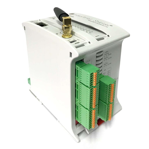
Current equivalentESP32 PLC 21 FLEX
An industrial controller built on the dual-core ESP32, for DIN rail, programmed with the Arduino IDE. It has Bluetooth LE built in for wireless sensors, and the FLEX version takes one communication board: here, 4G (M1)-NB1 IoT LTE for the link to the online application.
- Role
- Reads the sensors, converts the values, sends data and alarms, runs the remote commands
- Processor
- ESP32 dual core, up to 240 MHz
- Inputs
- 13: 6 analog/digital (0-10 V, 11-bit), 7 digital optoisolated (5 to 24 Vdc), 2 of them with interrupt
- Outputs
- 8: 3 analog/digital/PWM (0-10 V, 12-bit), 5 digital optoisolated (5 to 24 Vdc)
- Wireless
- Wi-Fi and Bluetooth LE built in; option board 4G (M1)-NB1 IoT LTE (u-blox), LoRa or CAN
- Wired
- Ethernet, RS-485, RS-232
- Programming
- Arduino IDE
- Power supply
- 12 to 24 Vdc
- Mounting
- DIN rail TS35, IP20, inside a cabinet
The 2020 study used a PLC with an Arduino Mega inside, a Bluetooth module and GPRS, and does not name the model. GPRS runs on 2G networks, which some operators have already switched off, so today the equivalent is the ESP32 PLC 21 FLEX with the 4G board. A well site is usually a hazardous area: the PLC goes in the safe area or in an enclosure certified for the zone, and the sensors must be certified for it too.
Questions about this case
How do you monitor an oil well remotely with a PLC?
Put a PLC at the well with the pressure, temperature and flow sensors, and a mobile link to an online application. The PLC reads the sensors at a fixed period, converts the raw values to units, checks the alarm levels and sends the data. In this case an ESP32 PLC 21 FLEX with a 4G board does it; the 2020 study used GPRS. You can try the same pattern of remote values and alarms in the remote site telemetry simulator.
Wireless sensors or 4-20 mA at a well site?
The study proposes Bluetooth sensors, to avoid wires at the well. At many industrial sites the usual choice is 4-20 mA transmitters, wired to the PLC: they are robust over long cables and many are certified for hazardous areas. The ESP32 PLC reads both: 4-20 mA through a shunt resistor or a converter on its 0-10 V inputs. See how an ESP32 PLC reads 4-20 mA pressure and temperature sensors.
Which safety layer works alongside the remote stop?
The remote stop and slow-down in this case are process commands: the PLC reads them from the mobile network and acts on the pump or the well control. The protection of the well and the people runs in its own layer: a safety instrumented system designed to IEC 61511 for the shutdown of the process, and local emergency stops that do not depend on the network. Equipment in hazardous areas follows IEC 60079 (ATEX or IECEx).
GPRS or 4G for a new remote site?
The study used GPRS in 2020. GPRS runs on 2G networks, which some operators have switched off or plan to. For a new site, check the coverage and the 2G end dates in the area. LTE-M and NB-IoT suit devices that send little data, and the ESP32 PLC 21 FLEX takes a 4G (M1)-NB1 IoT LTE board.
How does the PLC receive a command from the online application?
The application publishes the command, and the PLC checks it on every cycle and acts. A typical way is MQTT over the mobile link, with a confirmation back to the application. See remote commands over MQTT on an ESP32 PLC.
What does a petrochemical plant gain from this kind of monitoring?
The petrochemical study lists it: key indicators in real time, events by line, machine or installation (stop, breakdown, running, change, maintenance), stoppages anticipated, safety elements visible, alerts in both directions, no manual data entry, and dashboards for each level of responsibility. It does not publish figures.
Download the case study
4-page PDF with the challenge, the logic, the architecture and the hardware. No form required.
Similar project?
Tell us about your remote site. An engineer will answer.
Tell us what you need to measure, how far the site is, which network you have there and who must get the alarms. We will tell you which controller, which sensors and which link fit.
- You get an answer from our technical team
- Sensors, signals and the mobile link
- Arduino, ESP32 or Raspberry Pi based PLCs