Case study · Sector: HVAC OEM
One controller design. Every unit in the series.
An M-Duino 58 runs the fans, coils and dampers, and talks Modbus to the BMS.
An air handling unit leaves the factory with a controller that must work in a building nobody at the factory has seen.
So the OEM puts the same PLC in every unit, and each model, option and site becomes a set of parameters.
Based on real installations by customers in the sector; data and names are not published. Manufacturers of HVAC equipment build Industrial Shields controllers into their air handling units, in series. This page shows the architecture, the signals and the control sequences of that kind of unit. Set points, limits and messages are examples of a typical way to do it, not the settings of a real product.
The challenge
Many models, many options, one controller to support.
An OEM of air handling units sells a range of sizes, with or without heating coil, with an economizer or without, with one fan or two. Each unit goes to a different building, with a different building management system. The control engineer wants one controller and one program for the whole range, open enough to change, and with a clear map of data for the integrator of the building.
Hold the supply air
Keep the supply air temperature at its set point by sequencing heating, free cooling with outdoor air and mechanical cooling.
Move the right air
Hold the duct static pressure with the supply fan drive, and see when the filter needs a change.
Respect the safeties
Freeze and smoke protections stop the unit by wire. The controller must read them and bring the unit to a safe state.
Speak to the building
Give the BMS a fixed map: states, measures, alarms and the commands it is allowed to send.
One program for the range
Size, coils, fans and options are parameters set at the end of the line, not a different program for each unit.
How it works
Three jobs of the unit controller: temperature, air, safety.
Each panel shows one job of the PLC. Press the buttons. They are illustrative simulations: set points, limits and messages are examples, not data from a real unit.
Heating, free cooling, cooling: one sequence for the supply air.
The PLC compares the supply air temperature with its set point and runs one sequence: first the heating valve, then the outdoor air damper for free cooling, then the cooling valve. The outdoor air temperature decides if free cooling is worth it. Try a cold morning, a mild day, an economizer day and a hot afternoon.
- Supply air set point, PI loop
- Heating, economizer and cooling in sequence
- Minimum outdoor air always kept
- Outdoor temperature enables the economizer
Unit controller (example)
- Unit 2: occupied, supply set point 16 °C.
Illustrative simulation. Example values, no data from a real unit. Example values: supply set point 16 °C, minimum outdoor air 20 %. The real sequence and limits depend on the unit and the building.
Run the comfort, the fresh air and the alarms of four zones in the Building zones simulator
The fan holds the duct pressure. The filter tells when it is dirty.
The supply fan drive follows the duct static pressure: when the zone boxes close, the pressure rises and the fan slows down. The PLC also reads the pressure across the filter, and checks that each fan really runs after a start command. Close the boxes, clog the filter and make the fan fail.
- Duct static pressure, PI loop on the drive
- Filter alarm on differential pressure
- Fan proof: status must follow the command
- Drive fault read from the drive
Fans and filter (example)
- Duct pressure set point 250 Pa.
Illustrative simulation. Example values, no data from a real unit. Example values: duct set point 250 Pa, filter alarm at 300 Pa, fan proof after 20 s. Each model has its own values.
The safety chain stops the unit. The PLC makes it safe and tells the BMS.
Freeze and smoke protections are wired to stop the fans without waiting for the program. The PLC reads their state, closes the outdoor air damper, opens the heating valve on a freeze trip and sends the alarm. The BMS sees all of it in the Modbus TCP map, and can set occupied or unoccupied mode.
- Hardwired safety chain, read by the PLC
- Safe positions for dampers and valves
- Occupied and unoccupied mode from the BMS
- Alarms and states in a fixed Modbus TCP map
Safety and BMS (example)
- BMS polling the unit over Modbus TCP.
Illustrative simulation. Example values, no data from a real unit. Example values: freeze stat at about 4 °C across the face of the coil. Freeze and smoke actions follow the design and local codes of each project.
Poll Modbus slaves and serve a BMS map in the Modbus network simulator
System architecture
How does a PLC control an air handling unit built in series?
An M-DUINO ETHERNET PLC ARDUINO 58 sits in the control panel of the unit. It reads the air temperatures, the duct static pressure, the air quality, the filter, the state of the fans and drives, and the state of the safety chain. It drives the fan speeds, the coil valves and the dampers, and gives the building management system a fixed Modbus TCP map over Ethernet.
| Signal | Between | Type | Purpose |
|---|---|---|---|
| Supply, return, outdoor, mixed air temperature | BetweenTransmitters → M-Duino 58 | TypeAnalog 0-10 V | PurposeSupply air loop, economizer, freeze watch |
| Duct static pressure | BetweenTransmitter → PLC | TypeAnalog 0-10 V | PurposeFan speed loop |
| CO2 and humidity | BetweenReturn air sensors → PLC | TypeAnalog 0-10 V | PurposeOutdoor air and comfort |
| Filter pressure drop | BetweenTransmitter or switch → PLC | TypeAnalog or digital | PurposeMaintenance alarm |
| Fan running, drive fault | BetweenDrives → PLC | TypeDigital in, or Modbus RTU (typical) | PurposeFan proof and faults |
| Freeze stat, smoke detector | BetweenSafety chain → PLC | TypeDigital in, read only | PurposeSafe positions and alarms |
| Fan speed | BetweenPLC → supply and return drives | TypeAnalog 0-10 V, or Modbus RTU | PurposeHold duct pressure |
| Coil valves | BetweenPLC → cooling and heating valves | TypeAnalog 0-10 V | PurposeSupply air temperature |
| Dampers | BetweenPLC → outdoor and return air actuators | TypeAnalog 0-10 V | PurposeMinimum air and free cooling |
| Fan start, stages, alarm relay | BetweenPLC → panel | TypeDigital out | PurposeCommands and signalling |
| States, measures, commands | BetweenPLC ↔ BMS | TypeModbus TCP over Ethernet | PurposeBuilding integration |
Why it works
Enough I/O for the unit, open enough for the range.
All the unit in one PLC
With 36 inputs and 22 outputs, 16 of them analog in and 8 analog out, one M-Duino 58 covers the sensors and actuators of a typical unit.
Parameters, not versions
Size, coils, fans and options live in parameters set at the end of the line, so one program serves the range.
Safeties stay hardwired
Freeze and smoke protections stop the fans by wire. The PLC adds the safe positions and the alarms, it does not replace the chain.
A map the integrator can use
The BMS integrator gets a fixed Modbus TCP map, the same in every unit of the series.
Open programming
The M-Duino is programmed with the Arduino IDE, so the OEM keeps its own code and can change it.
Built for a panel
DIN rail, 12 to 24 Vdc, a real-time clock for schedules and a microSD slot for logs.
Hardware
One M-Duino 58 in the control panel of each unit.
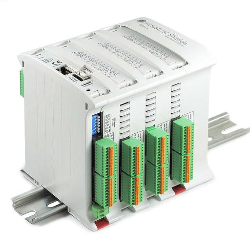
M-DUINO ETHERNET PLC ARDUINO 58
An industrial PLC based on Arduino, with 58 I/O and Ethernet, for DIN rail. It is the unit controller: control loops, sequences, safe positions and the Modbus TCP map for the BMS.
- Role
- Unit controller: supply air, fans, dampers, coils, safeties and BMS map
- Microcontroller
- Arduino Mega 2560 (ATmega2560, 16 MHz)
- Inputs
- 36: 16 analog/digital (0-10 V, 10-bit) and 20 digital optoisolated, 5 to 24 Vdc, 6 with interrupt
- Outputs
- 22: 8 analog/digital/PWM (0-10 V, 8-bit) and 14 digital optoisolated, 5 to 24 Vdc
- Communications
- USB 2.0 Type-B, Ethernet (W5500, 10/100), RS-485, RS-232, TTL, I2C, SPI
- Power and mounting
- 12 to 24 Vdc, DIN rail TS35, IP20, 0 to 60 °C; real-time clock and microSD slot
Temperature probes such as NTC or Pt1000 need transmitters to 0-10 V, or a temperature input module. The digital outputs are transistor outputs at 24 Vdc: use interface relays for contactors and compressor stages. If the building asks for BACnet, a protocol gateway next to the PLC translates the Modbus TCP map. Many unit panels supply 24 Vac: feed the PLC from a 24 Vdc DIN rail supply.
Questions about this case
Can a PLC be the controller of an air handling unit built in series?
Yes. An M-Duino 58 has the analog inputs for the air temperatures and pressures, the analog outputs for drives, valves and dampers, and Ethernet for the BMS. The OEM writes one program for the range and sets each unit with parameters at the end of the line.
What is the control sequence of the supply air temperature?
A typical sequence uses one loop on the supply air temperature and splits its output: first the heating valve, then the outdoor air damper for free cooling, then the cooling valve. The outdoor air temperature enables or blocks the economizer, and the damper never goes below the minimum outdoor air.
Does the PLC replace the freeze stat and the smoke detector?
No. They stay wired in the safety chain and stop the fans by themselves. The PLC reads their state, puts the dampers and valves in safe positions, and sends the alarm to the BMS. The actions follow the design of the unit and the local codes.
How does the BMS read the unit?
Over Modbus TCP on Ethernet, with a fixed register map: measures, states, alarms and the commands the BMS may write, such as occupied mode or the set point. See a Modbus TCP register map on an M-Duino. If the building needs BACnet, a gateway translates the map.
How does the PLC control the fan drives?
With a 0-10 V speed signal and a start command, or over Modbus RTU on RS-485 when the drive supports it, which also gives speed, current and faults. See VFD speed control over Modbus on an M-Duino and chiller control over Modbus RTU.
How is this different from the shopping mall HVAC story?
The shopping mall success story is one HVAC unit built for one building by an integrator, with a Raspberry PLC. This page is about an OEM that builds air handling units in series and puts the same controller in all of them.
Download the case study
4-page PDF with the challenge, the logic, the architecture and the hardware. No form required.
Similar project?
Tell us about your units. An engineer will answer.
Tell us the range of units, the sensors and actuators per model, the options and what the buildings expect from the BMS link. We will tell you which controller, which I/O and which data map fit.
- You get an answer from our technical team
- I/O per model, sequences and BMS maps
- Arduino, ESP32 or Raspberry Pi based PLCs