Case study · Geothermal energy · M-Duino 58
Watch the heat pump. Protect the plant.
Manifold sensors, pumps, valves, alarms and data on one M-Duino 58.
Sensors see pressure and temperature.
The PLC keeps the system inside its limits.
This page is a reference design, not a project report. The source describes how a PLC can control and monitor the heat pumps of a geothermal installation. It does not name a plant or a customer, and it does not publish measured results. Use it as a pattern you can adapt.
The challenge
Heat from the ground, inside safe limits.
Geothermal energy is the heat stored beneath the surface of the earth. It is renewable, but two things are critical for it to be viable and efficient: temperature control and efficient monitoring. High pressure and high temperature also wear the mechanical parts fast. The source covers both: the plant that takes the heat from the ground and the heat pumps that use it. The goal: a PLC that controls and monitors the heat pumps, protects the equipment and keeps the data.
Water or steam
The first variables are the temperature and the flow of the water or the steam.
A reservoir that lasts
Manage the reservoir in a sustainable way, so its capacity does not degrade over time.
Heat pump and plant
Detect abnormal or hazardous conditions before they damage the heat pump or the plant.
Wear under pressure
High temperature and high pressure wear the mechanical parts fast. Maintenance must be preventive and predictive.
Grid demand and regulations
The energy that goes into the grid has to follow a demand that changes. Energy policies and regulations also ask for control of the energy consumption and other factors.
How it works
Three loops: regulate, protect, then record and connect.
Each loop shows one part of the pattern. Move the sliders and press the buttons. The panels are illustrative simulations: temperatures, pressures, flows, levels and records are examples, not data from a plant.
Sensors on the manifolds. Pumps and valves on the outputs.
The PLC reads sensors on the heat pump manifolds and on other critical parts of the system: pressure, temperature and other abnormal conditions. It also drives the actuators that regulate the pumps, the valves and other mechanical equipment, and adjusts them as needed. Its control program decides how to answer each signal, to keep the system inside the set parameters. A typical way to do it: a PI loop that sets the speed of the circulation pump to hold the temperature difference (ΔT) across the manifold. Change the heat demand and watch the PLC answer.
- Pressure and temperature sensors on the heat pump manifolds
- Pumps, valves and other mechanical equipment on the outputs
- A control program that keeps the set parameters
Illustrative simulation. Example values, no data from a plant. Example: ΔT set point 5 K. The speed of the circulation pump comes from an analog output (0-10 V).
First an alarm. Then, if needed, an emergency shutdown.
Safety is part of the program. When a value leaves its limits, the PLC can trigger an alarm. When the condition is hazardous, it can start an emergency shutdown procedure, to prevent damage to the equipment or a safety hazard. A typical way to do it: two levels for each value, an alarm level and a trip level, a check for a broken sensor wire, and a manual reset after a trip. Raise the pressure, or cut the sensor wire.
- Alarms for abnormal or hazardous conditions
- Emergency shutdown procedure from the PLC
- A record of every event
Event log (example)
Illustrative simulation. Example values, no data from a plant. Example levels: alarm at 6 bar, trip at 8 bar. After a trip, an operator resets the system when the pressure is back to normal.
Data for maintenance. One network for many plants.
The PLC collects and stores operational data for historical analysis, performance optimisation and strategic decisions. In the source, the data goes to the cloud, where forecasts help to plan preventive and predictive maintenance. With the same model, several geothermal plants can join one centralised and automated network. The source does not publish the link. A typical way to do it: keep each record on the microSD card, send it when the link is up, and send the waiting records after a cut. Choose a link, then cut it.
- Operational data stored with a timestamp
- Forecasts in the cloud for preventive and predictive maintenance
- Several plants on one centralised network
Records sent (example)
Illustrative simulation. Example values, no data from a plant. Example records. The source does not publish the link, the protocol or the data format.
System architecture
How does a PLC control a geothermal heat pump system?
In this layout, pressure, temperature and flow sensors on the heat pump manifolds go to the analog inputs of the M-Duino 58. Its outputs drive the pumps and the valves, the alarm and the emergency shutdown. RS-485 can read meters and other local devices. Ethernet or Wi-Fi takes the data to the plant network and the cloud server, and LoRa can link remote sites. The source names these links but does not publish which one carries which data.
| Signal | Between | Type | Purpose |
|---|---|---|---|
| Pressure | BetweenSensors on the heat pump manifolds → M-Duino 58 | TypeAnalog in (example) | PurposeAbnormal or hazardous conditions. Range not published |
| Temperature | BetweenSensors on the manifolds and critical parts → M-Duino 58 | TypeAnalog in (example) | PurposeTemperature control. Range not published |
| Flow of water or steam | BetweenFlow sensor → M-Duino 58 | TypeNot published | PurposeOne of the variables of the extraction process |
| Pumps and valves | BetweenM-Duino 58 → pumps, valves, other mechanical equipment | TypeOutputs | PurposeRegulate the operation and adjust it as needed. Signal types not published |
| Alarm and shutdown | BetweenM-Duino 58 → alarm, emergency shutdown procedure | TypeOutputs | PurposePrevent equipment damage and safety hazards |
| Operational data | BetweenM-Duino 58 → cloud server | TypeNot published | PurposeHistorical analysis, optimisation, forecasts for maintenance |
| Several plants | BetweenEach plant ↔ central system | TypeNot published | PurposeOne centralised and automated network (next step in the source) |
Why it works
One controller for control, protection and data.
Many signals on one PLC
The M-Duino 58 has 36 inputs, 16 of them analog (0-10 V), and 22 outputs, 8 of them analog or PWM. Sensors, pumps, valves and alarms of one installation can fit on one controller.
Protection in the program
Alarm levels, trip levels and the shutdown sequence live in the same control program that regulates the system.
Data that stays
A real-time clock and a microSD slot let the PLC timestamp events and log data locally, before it goes to the cloud.
The link that fits the site
Ethernet and RS-485 are built in. The M-Duino family datasheets describe versions with Wi-Fi & BLE, GPRS/GSM and LoRa.
Open code you own
You program it with the Arduino IDE. You own the application, because you know the code.
Modular
The specifications can grow later. Add I/O or another PLC on the same network when the installation grows.
Hardware used
In this design: one M-Duino 58.
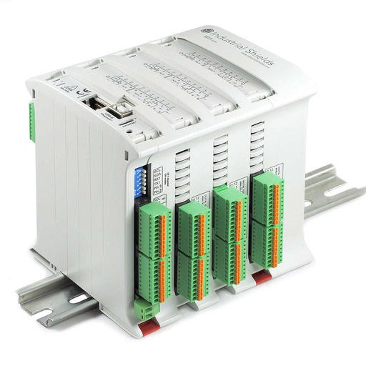
M-DUINO ETHERNET PLC ARDUINO 58
An industrial PLC built on an original Arduino Mega 2560, with 58 I/O, Ethernet and RS-485, for DIN rail. In this design it reads the manifold sensors, drives the pumps and the valves, raises the alarms and logs the data.
- Role
- Manifold sensors, pumps and valves, alarms, data log
- Inputs
- 36: 16 analog/
digital (0-10 V), 20 digital optoisolated, 6 with interrupt - Outputs
- 22: 8 analog/
digital/ PWM (0-10 V), 14 digital optoisolated - Comms
- Ethernet (W5500), RS-485, RS-232, TTL, I2C, SPI
- Extras
- Real-time clock, microSD slot
- Power and environment
- 12 to 24 Vdc, 0 to 60 °C, DIN rail TS35, IP20
The source shows an M-Duino with a LoRa antenna and lists Arduino based PLCs with up to 58 I/O and Ethernet, RS-232, RS-485, LoRa, NB-IoT and Wi-Fi. It does not publish one exact model. The card shows the M-DUINO ETHERNET PLC ARDUINO 58. Its LoRa and Wi-Fi & BLE versions are described in the family datasheets.
Questions about this case
How can a PLC control and monitor a geothermal heat pump system?
Put pressure and temperature sensors on the heat pump manifolds and on the other critical parts, and wire them to the PLC inputs. Wire the pumps, the valves and the other mechanical equipment to its outputs. The control program decides how to answer each signal and keeps the system inside the set parameters. It also raises alarms, starts an emergency shutdown when needed, and stores the operational data for analysis.
Which values should a geothermal installation watch?
The source names three: the temperature and the flow of the water or steam, the reservoir (so its capacity does not degrade over time), and the conditions that can damage the heat pump or the plant, such as pressure. Many transmitters give 4-20 mA. The analog inputs of the M-Duino 58 read 0-10 V, so a 4-20 mA loop needs a precision shunt resistor (500 Ω turns 20 mA into 10 V). Another option is transmitters with Modbus RTU on RS-485.
Can the PLC handle the emergency shutdown?
The source says that the PLC can trigger alarms or emergency shutdown procedures, to prevent equipment damage or safety hazards. In practice, the functions that protect people need a safety-rated circuit (for example a safety relay) designed to the standard that applies to your installation. The PLC starts the controlled shutdown, reports it and keeps the record. Mechanical protections, such as pressure relief valves, stay in place.
Ethernet, Wi-Fi, RS-485 or LoRa: which link sends the data?
The source does not publish the link. A typical choice: Ethernet where there is a cable, Wi-Fi where there is not, and RS-485 with Modbus RTU for meters and local devices (see Modbus RTU with Arduino and ESP32 based PLCs). LoRa reaches remote sites with low power, but it sends small packets at a low data rate, so send compact records and alarms. See how to work with LoRaWAN and a PLC controller. For a thermal machine on Modbus RTU with code, see Modbus RTU chiller control with an M-Duino PLC.
How does the data help with predictive maintenance?
The PLC collects and stores the operational data. In the source, it goes to the cloud, where forecasts help to plan preventive and predictive maintenance. A typical way to do it: log pressure, temperature, run hours and alarms with a timestamp, keep a copy on the microSD card, and look for trends that show wear before a failure.
Which parts of this page are facts, and which are examples?
Facts from the source: control and monitoring of heat pumps with a PLC; sensors on the heat pump manifolds and other critical parts for pressure, temperature and abnormal or hazardous conditions; actuators for pumps, valves and other mechanical equipment; control programs that keep the set parameters; alarms and emergency shutdown procedures; operational data for analysis and decisions; forecasts in the cloud for maintenance; the idea of one centralised network for several plants; and Arduino based PLCs with up to 58 I/O and Ethernet, RS-485, LoRa and Wi-Fi options. Examples: every value, set point, alarm level, trip level, record, link choice and plant on the panels.
Download the case study
4-page PDF with the challenge, the logic, the architecture and the hardware. No form required.
Similar project?
Tell us your heat pumps and your signals. An engineer will answer.
Tell us how many heat pumps or sites you have, which values you measure (pressure, temperature, flow), what the PLC must drive and where the data should go. We will tell you which controller fits and which link to use.
- You get an answer from our technical team
- I/O count and controller sizing for your installation
- Arduino, ESP32 or Raspberry Pi based PLCs