Case study · Fry hatchery · Arduino PLC
Spot fry disease early. PLCs watch the water.
Water, feeding and light under constant watch, on Arduino based PLCs.
A fry hatchery sells fish by their quality. Their health depends on the water, the food and the light.
So the PLCs watch those conditions and raise the alert early.
This case describes a monitoring system for disease detection in a fry hatchery, built with Industrial Shields PLCs. The case does not name the hatchery. The risk factors, the variables, the server, the cameras, the Boolean logic, the visual alerts, the response actions and the scheme with four PLCs on Modbus TCP come from the case. The limits and values in the panels are examples, not data from the hatchery.
The challenge
Keep every batch of fry healthy, with less human error.
The aim of a fry hatchery is to produce high quality fish for later sale. That needs constant control of the environment and the living conditions, for the welfare, the health and the growth of the fry, and to meet quality and animal welfare standards. The goal of the project: automate disease detection with PLCs in a monitoring system, to reduce human error and to prevent disease caused by four factors.
Temperature
Sudden changes or extreme temperatures stress the fry and make them more likely to get ill. The water temperature must stay constant and right for them.
Water quality
The water needs a suitable chemical composition and no contaminants. Regular monitoring finds problems before a disease starts.
Feeding
The fry need an adequate, balanced diet. A poor diet weakens their immune system and makes them more likely to get ill.
Lighting
Changes in the cycles of light and dark can alter their circadian rhythms, their behaviour and their metabolism. The light cycle must stay regular.
Why it matters
Manual tests and analysis take time and leave room for error. The case automates them: more accurate detection, an early diagnosis, and preventive measures before a disease spreads.
How it works
Three jobs: watch the water, decide the alert, respond.
Each panel shows one job. Press the buttons. The panels are illustrative simulations: the variables, the Boolean logic, the visual alerts and the response actions are the ones of the case, but every limit, value and rule here is an example, not data from the hatchery.
Temperature, salinity, pH and oxygen, all the time.
The sensors send their data to the PLCs all the time. Each PLC compares the readings with the limits and detects changes in the critical variables. Change the conditions and watch zone 1.
- Analog or digital sensors on each PLC
- Temperature, salinity, pH and dissolved oxygen
- A change in a variable is the first sign
Readings of zone 1 (example)
Illustrative simulation. Example values, not data from the hatchery. The case names temperature, salinity, pH and oxygen, read by analog or digital sensors, and does not publish the species or the limits. Example limits for a marine species: 18 to 22 °C, 30 to 36 ppt, pH 7.5 to 8.5, oxygen above 6 mg/L. Real limits depend on the species and the stage.
Boolean logic decides when to warn.
A reading out of range is not always a disease. The PLCs combine conditions with algorithms and Boolean logic, and only then light the visual signal for the operators. Switch the conditions on and off.
- Water out of range, and for how long
- Fish behaviour seen by the cameras
- A visual signal for the operators
Alert logic (example)
Illustrative simulation. Example values, not data from the hatchery. The case says the PLCs use algorithms and Boolean logic to decide when an alert fires, and that the alerts reach the operators as visual signals. It does not publish the rules. These two rules and the 10 minute delay are examples. Fish behaviour comes from the cameras of the case.
Stop the feed, fix the water, give the medicine.
Once an alert fires, the PLCs carry out the response actions set for it. An automatic dosing system gives the medicine with precision and control. Pick an alert.
- Stop the feed supply
- Adjust the water temperature or salinity
- Automatic dosing of medicine
Response (example)
Illustrative simulation. Example values, not data from the hatchery. The case names the actions: stop the feed supply, adjust the water temperature or salinity, or give medicine to the fry with an automatic dosing system, with precision and control. It does not publish the set points or who approves a treatment. In this example, a dose waits for an operator to confirm it, and the volumes are examples.
Try it on a full network
Practise with the network and the alarms.
The panels above show one zone. These simulators run the parts around it: a Modbus network of PLCs, and data and alarms from many sites.
Serve the readings over Modbus TCP
Poll slaves and serve Modbus TCP clients with a PLC. See frames, timeouts, stale values and word order: the same protocol that links the PLCs of this case to the panel.
Open the simulatorSimulator · Remote site telemetryAlarms from many sites, one operator
Practise how readings and alarms reach the operator, and what happens when a site fails. The example is a water network; the pattern of limits and alarms is the same.
Open the simulatorSystem architecture
How do PLCs detect disease in a fish hatchery?
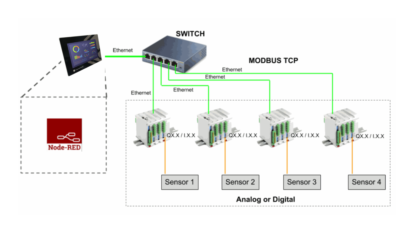
Put one PLC in each zone of the hatchery and connect its sensors: analog or digital, for temperature, salinity, pH and oxygen. Cameras watch the behaviour of the fish. The PLCs read the data all the time and detect changes. Link the PLCs to an Ethernet switch with Modbus TCP. A Panel PC with Node-RED shows and controls the system, and a server stores and processes the data. When the Boolean logic of a PLC fires an alert, it lights a visual signal and runs the response: stop the feed, adjust the water or dose the medicine.
| Signal | Between | Type | Purpose |
|---|---|---|---|
| Water temperature | BetweenSensor → PLC | TypeAnalog or digital | PurposeSudden changes or extremes stress the fry |
| Salinity | BetweenSensor → PLC | TypeAnalog or digital | PurposePart of the water quality |
| pH | BetweenSensor → PLC | TypeAnalog or digital | PurposePart of the water quality |
| Oxygen level | BetweenSensor → PLC | TypeAnalog or digital | PurposeA critical variable named by the case |
| Fish behaviour | BetweenCameras → analysis system | TypeVideo | PurposeA change can show a disease. The case does not publish how the images are analysed |
| Readings and states | BetweenPLCs → switch → Panel PC | TypeModbus TCP over Ethernet | PurposeCentral view and control with Node-RED |
| Data | BetweenSystem → server | TypeNot published | PurposeThe server stores and processes the data |
| Alert | BetweenPLC → operators | TypeVisual signal | PurposeFired by algorithms and Boolean logic |
| Response | BetweenPLC → feeder, water, dosing | TypeOutputs | PurposeStop the feed, adjust temperature or salinity, give medicine |
Why it works
The PLC watches all the time. People decide with better data.
Fewer human errors
The PLCs read every variable the same way, every time. The case expects more accurate detection than with manual tests and analysis.
Faster results
Automated tests and analysis take much less time. The results come sooner, and so does the response to an outbreak.
Logic you can read
The alert rules are Boolean logic in the PLC program: conditions, delays and combinations that the team can check and change.
One PLC per zone
The scheme of the case shows four PLCs on one Ethernet switch, each with its own sensors. In this design each PLC watches one zone, so a new zone is one more PLC and one more Modbus TCP address.
Open, no licence fees
The PLCs are programmed with the Arduino IDE and the panel runs Node-RED. Neither needs a licence.
Modular, with support
The system can grow later. Our team supports the project before, during and after the sale and the installation.
From the original case
The scheme of the case.
The case does not publish photos of the installation.
Hardware
The PLC of the case, today. And a panel for Node-RED.

Current equivalentM-DUINO ETHERNET PLC ARDUINO 38AR
One PLC per zone. It has analog inputs for the water sensors, relays for the feeder and the pumps, analog outputs for set points, and Ethernet for Modbus TCP.
- Role in this design
- Reads the sensors of one zone, runs the alert logic and the response actions
- Controller
- Arduino Mega 2560, programmed with the Arduino IDE
- Inputs
- 19: 10 analog/digital (0-10 V, 10-bit) and 9 digital optoisolated, 5 to 24 Vdc, 4 with interrupt
- Outputs
- 19: 8 relays (230 Vac 4 A), 6 analog/digital/PWM (0-10 V) and 5 digital optoisolated
- Communications
- Ethernet (W5500) with Modbus TCP, RS-485, RS-232, I2C, SPI
- Built in
- Real-time clock, microSD slot
- Power and mounting
- 12 to 24 Vdc, DIN rail TS35, IP20, 0 to 60 °C
The case used the M-Duino 54ARA (29 inputs, 14 of them analog; 25 outputs, 8 of them relays), no longer in the web shop. The M-Duino 38AR has the same kind of analog and relay modules, with fewer analog inputs. If a zone needs more, use one more PLC or ask our team. See the M-Duino family datasheet.
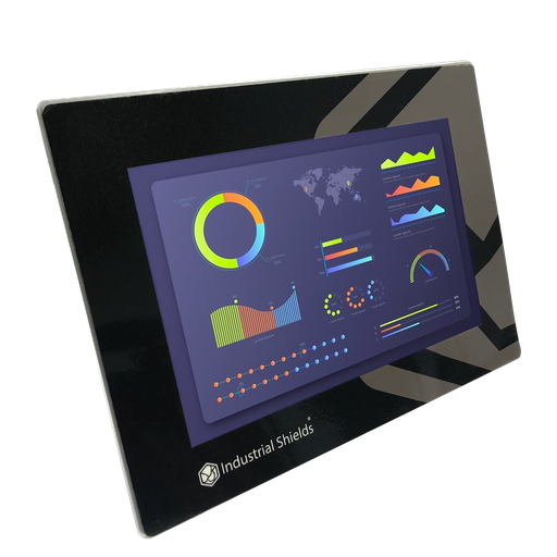
Option for the panelTouchBerry Pi Panel PC 10.1" FLEX
The scheme of the case shows a Panel PC running Node-RED, linked to the PLCs over Ethernet. The case does not publish its model. This panel PC runs Node-RED on a Raspberry Pi.
- Role in this design
- Node-RED dashboard: readings of every zone, alerts and control
- Screen
- 10.1" touchscreen
- Base
- Raspberry Pi
- Link to the PLCs
- Ethernet, Modbus TCP
Not named in the original case.
Questions about this case
Which water parameters should a fry hatchery monitor?
In this case the PLCs watch temperature, salinity, pH and oxygen level, and cameras watch the behaviour of the fish. The case also names feeding and lighting as risk factors for disease: a balanced diet and a regular cycle of light and dark. The right limits depend on the species and the stage of the fry.
How does a PLC read pH, oxygen and salinity sensors?
In this case the sensors are analog or digital. The M-Duino 38AR has 10 analog inputs of 0-10 V. A transmitter with a 4-20 mA output needs a shunt resistor (500 Ω turns 20 mA into 10 V). Sensors with Modbus RTU go to the RS-485 port. Check the output of each probe before you choose.
How do the PLCs decide when to raise an alert?
The case says they use a combination of algorithms and Boolean logic, and send the alerts to the operators as visual signals. It does not publish the rules. A typical way: a warning when a value leaves its range, and an alert when it stays out for some minutes or when the cameras see a change in behaviour. Try it in the second panel.
Can a PLC give medicine to the fry automatically?
The case plans an automatic dosing system that gives medicine with precision and control, as one of the response actions of the PLCs. The PLC runs the dosing pump until it gives the set volume. The treatment itself is a decision of the hatchery and its vet; the case does not publish who approves it. In the example on this page, a dose waits for an operator to confirm it.
Why link the PLCs with Modbus TCP?
In the scheme of the case, every PLC is on one Ethernet switch, and the Panel PC with Node-RED reads them with Modbus TCP. Each PLC keeps running on its own, and the panel gets every reading and state. More sensors or zones are one more PLC on the switch. See a Modbus TCP register map for a plant.
Which parts of this case are facts and which are examples?
Facts of the case: the four risk factors, the five critical variables, the server, the cameras and digital sensors, the Boolean logic, the visual alerts, the response actions, the automatic dosing system and the scheme with a Panel PC with Node-RED and four PLCs on Modbus TCP. Examples: every limit and value, the alert rules, the 10 minute delay, the dose confirmation and the volumes.
Download the case study
4-page PDF with the challenge, the logic, the architecture and the hardware. No form required.
Monitoring tanks of fish?
Tell us about your hatchery. An engineer will answer.
Tell us the species, how many tanks or zones you have, which variables you measure and what the system must do when something goes wrong. We will propose the PLCs, the network and the panel.
- You get an answer from our technical team
- Sensors, PLCs and alert logic for each zone
- Arduino, ESP32 or Raspberry Pi based PLCs