
A PLC (programmable logic controller) is an industrial controller that reads sensors through its inputs, runs a control program and switches actuators through its outputs. It repeats this read, execute and write sequence in a fixed cycle, called the scan, so the machine reacts to every change of its signals.
This guide explains the parts of a PLC, the scan cycle, a first program, the IEC 61131-3 languages, the types of PLC and where they are used. It also compares a PLC with a microcontroller board and an industrial PC. An example of an Arduino-based programmable logic controller is the M-Duino 21.
What is a PLC?
The standard IEC 61131-1 describes a programmable controller as a digital electronic system designed for an industrial environment. It stores the user program in memory and uses it for logic, sequencing, timing, counting and arithmetic, to control machines or processes through digital and analog inputs and outputs.
In practice, a PLC replaces the relay logic that controlled machines before. PLCs appeared at the end of the 1960s in car factories: changing a production line meant rewiring relay panels. With a PLC, you change the program instead of the wiring.
A PLC is defined by how it works, not by its processor: one control program that runs in a repeating cycle, with industrial inputs and outputs, built to run without stops inside an electrical cabinet.
A simple example: a pressure sensor is wired to an input. The program compares the value with a limit. When the pressure goes above the limit, the PLC switches on an output that drives an alarm beacon, and it switches it off when the pressure goes back to normal.
Parts of a PLC: CPU, memory, inputs, outputs and communication ports
Every PLC has the same blocks, whatever the brand or the processor.
| Part | What it does | Typical example |
|---|---|---|
| CPU | Runs the control program and the scan cycle. | A microcontroller or a microprocessor: an ATmega2560 (Arduino Mega) in an M-Duino Arduino PLC, an ESP32 in an ESP32 PLC, a Raspberry Pi in a Raspberry PLC. |
| Memory | Stores the program, the variables and the values that must survive a power cut. | Flash for the program, RAM for variables, non volatile memory for counters and set points. |
| Inputs | Read the state of the process. | Digital: push buttons, limit switches and proximity sensors at 24 V DC. Analog: 0-10 V or 4-20 mA from pressure, level or temperature transmitters. |
| Outputs | Act on the process. | Relay or transistor outputs for contactors, solenoid valves and beacons. Analog outputs for the speed set point of a VFD. |
| Power supply and communication ports | Feed the PLC and connect it to other devices. | 24 V DC supply. RS-485 for Modbus RTU, Ethernet for Modbus TCP or MQTT, CAN. |
To read a 4-20 mA transmitter, see how to convert a 4-20 mA signal to 0-10 V in an Arduino PLC. For serial links, see the basics of RS-485 on an industrial PLC and the communication protocols used in industrial automation.
The PLC scan cycle, step by step
A PLC does not react to an input at the exact moment it changes. It works in a loop with four steps:
- Step 1Read inputsCopies the state of all inputs into memory: the input image.
- Step 2Run the programRuns the program from start to end with that copy of the inputs.
- Step 3Write outputsCopies the results to the physical outputs.
- Step 4HousekeepingCommunications, diagnostics and the watchdog. Then the cycle starts again.
The time of one loop is the scan time. It depends on the CPU and on the size of the program, and it is usually in the range of milliseconds. A signal shorter than one scan can be missed. This is why fast pulses, for example from encoders or flow meters, go to high speed counter inputs or interrupts, not to the normal program. See a production pulse counter with interrupts on an ESP32 PLC.
The watchdog is a timer that the CPU must reset in every scan. If the program blocks, for example in a long wait, the watchdog expires and the PLC stops or restarts in a known state. For this reason, PLC programs never wait inside the logic: they use timers that are checked in every scan. The same rule applies to Arduino code, as explained in millis() vs delay() in an industrial Arduino and in the hardware watchdog example for unattended machines.
A first PLC program: tank level control in Structured Text
A water tank has a level transmitter, a fill pump and a high level beacon. The pump starts below 400 mm and stops above 1800 mm. The beacon turns on above 1950 mm. The gap between the start level and the stop level (hysteresis) keeps the pump from switching on and off all the time.
VAR
    Level_mm  : INT;   (* from a 4-20 mA level transmitter *)
    Pump      : BOOL;  (* digital output to the pump contactor *)
    HighAlarm : BOOL;  (* digital output to a beacon *)
END_VAR

IF Level_mm <= 400 THEN
    Pump := TRUE;      (* low level: start filling *)
ELSIF Level_mm >= 1800 THEN
    Pump := FALSE;     (* high level: stop filling *)
END_IF;

HighAlarm := Level_mm >= 1950;
Between 400 and 1800 mm, the program does not write Pump, so the output keeps its last state. The PLC runs these lines in every scan. In Ladder Diagram, the same logic is three rungs: a comparison that sets the pump coil, a comparison that resets it, and a comparison that drives the beacon.
A complete version with float switches on an ESP32 PLC is in the PLC Solution Library: water pump control with float switches.
IEC 61131-3 PLC programming languages
IEC 61131-3 is the international standard for PLC programming languages. The current edition, IEC 61131-3:2025, defines three languages (LD, FBD and ST) and the Sequential Function Chart (SFC), which structures a program in steps and transitions:
| Language | Type | Typical use |
|---|---|---|
| Ladder Diagram (LD) | Graphical: contacts and coils | Discrete logic and interlocks. Easy to read for electricians and maintenance teams. |
| Function Block Diagram (FBD) | Graphical: blocks and connections | Analog signal processing and PID loops. |
| Structured Text (ST) | Textual, similar to Pascal | Calculations, data handling and state machines. |
| Sequential Function Chart (SFC) | Graphical: steps and transitions | Machine sequences: batching, filling, start up and stop. |
The 2013 edition also included Instruction List (IL), a low level text language that you still find in older programs.
CODESYS and OpenPLC are two IEC 61131-3 environments: see how to set up CODESYS on a Raspberry PLC (experimental), Ladder programming with CODESYS (experimental) and first steps with OpenPLC. PLCs based on open hardware can also be programmed in C++ with the Arduino IDE (how to install the Industrial Shields boards) or in Python and Node-RED on Linux (Modbus examples for Raspberry PLC).
PLC, microcontroller board and industrial PC compared
Engineers often ask if an Arduino or an ESP32 board can do the job of a PLC. The processor can be the same. What changes is everything around it.
| Criterion | PLC | Microcontroller board | Industrial PC |
|---|---|---|---|
| Main job | Deterministic control of machine inputs and outputs | Prototypes and embedded products | Data, HMI, databases and vision |
| Signal levels | 24 V DC digital, 0-10 V and 4-20 mA analog, relay or transistor outputs | 3.3 V or 5 V logic pins. Interface boards are needed for 24 V signals. | Separate I/O modules or a fieldbus |
| Electrical environment | Designed for the noise and wiring of an electrical cabinet (IEC 61131-2) | No protection on the bare board | Industrial versions exist |
| Mounting and supply | DIN rail, 24 V DC | PCB, USB or 5 V | DIN rail or panel |
| Program model | Scan cycle with watchdog | Free loop written by the developer | Operating system with tasks. A soft PLC runtime adds the scan cycle. |
| Programming | IEC 61131-3 tools. C++ or Python on open hardware PLCs. | C or C++ (Arduino IDE), MicroPython | Any language |
An Arduino PLC or an ESP32 PLC is a microcontroller inside a PLC: the same chip as the board, with industrial inputs and outputs, a DIN rail enclosure and a 24 V DC supply. You keep the Arduino IDE and its libraries, and you wire it like any other PLC. A Raspberry PLC sits between the PLC and the industrial PC: Linux with PLC inputs and outputs, so Node-RED or Python can run next to the control logic.
More on this question in Is Arduino suitable for industry?.
Types of PLC: compact, modular, safety, soft PLC and open hardware
- Compact PLC: CPU, inputs, outputs and power in one housing, with a fixed number of I/O. Common in small machines.
- Modular PLC: CPU and I/O cards on a rack or a bus. You add cards when the machine grows.
- Safety PLC: certified for safety functions such as emergency stops, light curtains and safety doors, with redundant channels and diagnostics. A standard PLC does not replace it.
- Soft PLC: a PLC runtime on a PC or an embedded Linux device, for example CODESYS.
- Open hardware PLC: an industrial PLC built on Arduino, ESP32 or Raspberry Pi, programmed with open tools.
Industrial Shields builds open hardware PLCs in three families:
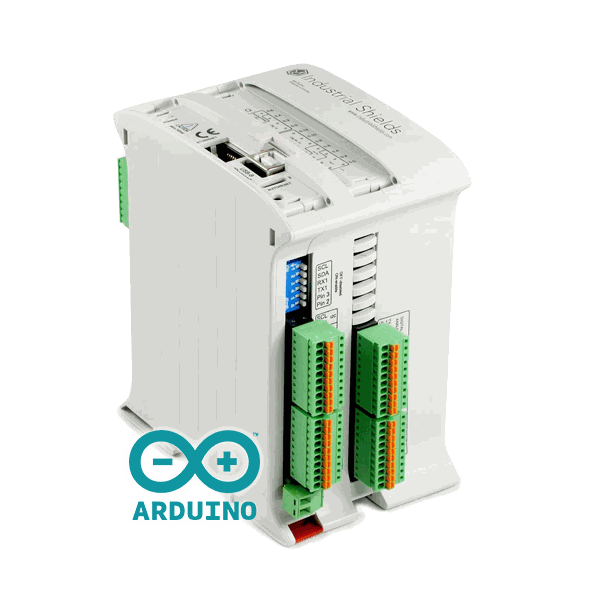
Arduino PLC
M-Duino Arduino PLC (Arduino Mega) and Ardbox Arduino PLC (Arduino Leonardo). Programmed with the Arduino IDE or OpenPLC.
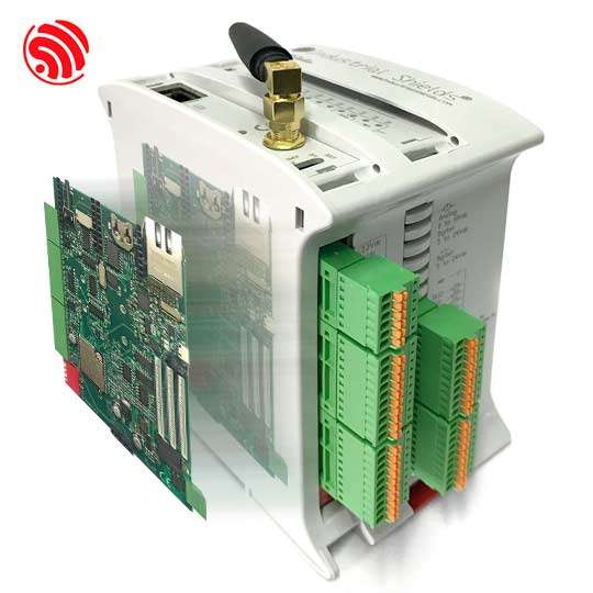
ESP32 PLC
Dual core ESP32. Programmed with the Arduino IDE or OpenPLC.
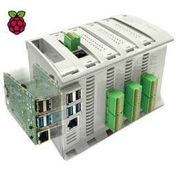
Raspberry PLC
Raspberry Pi with Linux. Node-RED and Python on the same device.
To choose between them, read Arduino PLC vs ESP32 PLC vs Raspberry Pi PLC. To use OpenPLC on any of them, see ESP32 PLC, M-Duino Arduino PLC and Ardbox Arduino PLC with OpenPLC.
PLC applications by sector
A PLC can control any process that you can describe with signals and rules. These are the most common applications, with real projects where they exist.
| Sector | What the PLC does | Example project |
|---|---|---|
| Filling, packaging and labelling (food and drink, paper, glass) | Fills by level or weight, drives conveyors, counts products and stops the line on a fault. | Bottle labelling conveyor, packaging line traceability |
| Motors and conveyors | Start and stop, interlocks, speed set point to a VFD over Modbus or 0-10 V. | Conveyor belt VFD speed control |
| Water and pumping | Tank level, pump alternation, pressure control in multi pump stations, well drainage and alarms. | Water treatment with ESP32 PLC |
| Process plants | Batching sequences and boiler control loops. Burner flame safety stays in a certified burner control unit. | Concrete batching plant, steam boiler automation |
| Energy and substations | Remote breaker commands, capacitor bank switching, fault and event logging, solar inverter monitoring. Protection tripping stays in the protection relays. | Fronius SunSpec Modbus TCP monitoring |
| Remote sites and mining | Remote control and line monitoring of equipment, with telemetry over 4G or LoRaWAN. | Remote site telemetry simulator |
| Buildings and services | HVAC, car washes, parking areas, automatic doors, traffic lights and water tanks. | Automatic car wash, HVAC immersion cooling |
More sectors and examples in the top 50 industrial applications.
Next steps to program a PLC
- Software: tools to program Industrial Shields PLCs (Arduino IDE, OpenPLC, Node-RED).
- Examples: PLC Solution Library, with tested code, and PLC simulators to see control logic run in the browser.
- Courses: programming Arduino in industrial environments and the Industrial Shields YouTube channel.
- Blogs: Arduino industrial blog and Raspberry Pi for industry blog.
Do you have a machine or a process to automate? Tell us the signals and the protocols, and an engineer will suggest a PLC model.
FAQ about PLCs
What does PLC stand for?
PLC stands for programmable logic controller. The standards call it a programmable controller. In Spanish it is also called an autómata programable.
Is a PLC a computer?
Yes, a specialised one. It has a CPU, memory and a program, but it is built for one control task: industrial inputs and outputs, a cyclic program and operation without stops.
What is the difference between a PLC and SCADA?
The PLC controls the machine in real time. SCADA is software that supervises one or more PLCs: screens, alarms, history and set points. SCADA reads and writes PLC data over protocols such as Modbus TCP, OPC UA or MQTT. If SCADA stops, the PLC keeps controlling the machine.
Which PLC language should I learn first?
Ladder Diagram, if you work with discrete logic and maintenance teams. Structured Text, if you come from software or need calculations. Many projects use both.
Can an Arduino be used as a PLC?
A bare Arduino board can run control logic, but it has 3.3 V or 5 V pins, no protection against the noise of a cabinet and no DIN rail mounting. An Arduino PLC adds industrial inputs and outputs, a 24 V DC supply and an enclosure, and keeps the Arduino IDE.
How fast is a PLC?
It depends on the scan time, which depends on the CPU and on the program size. Signals faster than one scan go to high speed counter inputs or to interrupts.