Technical Features
WIS-PLC
Initial installation
Arduino IDE
Arduino IDE is the original platform to program Arduino boards. This cross-platform application is available on Windows, macOS and Linux under the GNU General Public License. Arduino IDE supports C and C++ code structuring. In order to program the ESP32 based PLCs in this environment, Industrial Shields provides a boards package with the necessary libraries and tools.
We recommend using the Legacy Arduino IDE (1.8.X) to program ESP32 based PLCs, although other ESP compatible software could be used. The Arduino 1.8.X IDE can be downloaded from this link. After downloading and installing the Arduino IDE, install the industrialshields-wis-esp32 or the industrialshields-wis-samd boards package depending on the CPU of your WIS-PLC. This can be done by following this tutorial and selecting the corresponding package in step number 6.
Power supply
The WIS-PLCs need to be powered with an external power supply, providing a voltage between 12 and 24Vdc. Caution! Although at first glance it may seem like the PLC works when powered with the USB port, this is not the case. The usage of an external power supply is mandatory for the PLC to perform properly.
The measured consumption for the WIS-PLC is between 40mA and 74mA, but a supply with a minimum of 0,8A is recommended to achieve good performance.
PSU specifications:
- Voltage: between 12 and 24Vdc.
- Intensity: at least 0,8A.
The diagram in this section illustrates the necessary connections to properly power a PLC.

Device Overview
Here's a quick overview of the WIS-PLC's pinout:
Left view:

Right view:

DIP Switches
Weidos devices have two DIP switches (SW1 and SW2) on one side. These switches are meant for selecting the operational mode of the Serial RS485/UART connector and the Multifunction pins.

To use the serial port as RS485 or UART function the pins have to be configured this way:

To switch Multifunction pins signal between 3,3 have the pins configured like this:

The positions of pins not shown in the table are not relevant.
Attention: disconnect the WIS-PLC from the power supply before doing any change to the DIP switches configuration.
Power consumption
Current (mA) | Power (W) | |
Idle | 51,34 | 1,23 |
Full workload | 73,9 | 1,77 |
Inputs & Outputs
Digital inputs
Digital inputs are used to capture signals that exist in one of two states: high or low, true or false, etc. The WIS-PLC digital inputs interpret as high values of 5 Vdc or higher, up to 24 Vdc, whereas values lower than 3,3V are interpreted as low.
Digital Input pins are located on the following connector:

Typical wiring connection for digital inputs using voltage signal from main Power Supply:

In order to use them, the digital inputs don't need to be configured in the set up part of the code. Then they can be read using the "digitalRead()" function, with the input name as its parameter. For example, DI_4:
Analog/Digital Inputs
The use of these inputs as analog or digital is selected via software by programming with the built-in functions analogRead() or digitalRead(). They do not depend on any external switch or additional hardware configuration. As Digital Inputs, these pins will detect HIGH state between 5 and 24Vdc, in the same way as in the opto-isolated digital inputs. As Analog Inputs, these pins will detect the analog signal between 0 and 10Vdc with a resolution of 12 bits by default (lower resolution can be set via software).
Typical wiring connection:

The maximum value of the analogRead is 4096, which represents 10V. This is how to read them as both digital and analog:
Digital Outputs
The WIS-PLC digital outputs can provide a low (0 Vdc) or high (up to Vin - 1) value. The high value comes from the voltage that is supplied to the WIS-PLC through Vin+, which can range from 11,4V to 25,4V. These outputs are labeled as DO_X, and are located on the following connectors:

Typical wiring connection:

Example blink code:
Analog Outputs
The WIS-PLC has a single analog output pin that can range from 0V to 10V. This is where it is located:

Typical wiring connection:

When coding in Arduino IDE, the values will range between 0 and 1024. This example code will output a signal of 5V:
Communications
Ethernet
Ethernet is the most commonly used technology in wired local area networks ( LANs ).
A LAN is a network of computers and other electronic devices that covers a small area such as a room, office, or building. It is used in contrast to a wide area network (WAN) , which spans much larger geographical areas. Ethernet is a network protocol that controls how data is transmitted over a LAN. Technically it is referred to as the IEEE 802.3 protocol. The protocol has evolved and improved over time to transfer data at the speed of a gigabit per second.
The WIS-PLCs incorporate an Ethernet port, using the W5500 controller, which communicates with the CPU using SPI. The W5500 is a Hardwired TCP/IP embedded Ethernet controller that provides easier Internet connection to embedded systems. This chip enables users to have Internet connectivity in their applications by using the single chip in which TCP/IP stack, 10/100 Ethernet MAC and PHY are embedded. With this chip users can integrate Ethernet into their applications.
Hardware setup
Remember to properly power the PLC with a 12-24V power supply.
Software setup
The Industrial Shields boards package includes an "Ethernet" library, intended to facilitate the use of this protocol. Various examples are included with the library, you can check them out going to File > Examples > Examples for WIS -> ETHERNET inside the Arduino IDE.
It's important to do Ethernet.init(ETHERNET_CS) or the connection will not work. This is the StaticIPconfig example, which initializes the Ethernet shield and connects to the network with Static IP. It also checks for the presence of the shield and if the Ethernet cable is connected. If properly configured, it periodically prints the IP address:
#include <Ethernet.h>
byte mac[] = {0xDE, 0xAD, 0xBE, 0xEF, 0xFE, 0xED};IPAddress ip(192, 168, 1, 110); // user defined Static IP
IPAddress myDns(8, 8, 8, 8);
IPAddress gateway(192, 168, 1, 1);
IPAddress subnet(255, 255, 255, 0);
void setup() { Serial.begin(115200); // begin Serial
while(!Serial){} // wait for the Serial to be opened. Serial.println("Example will run after 5 seconds.");delay(5000);
Serial.println("Trying to connect. It can take a while!");Ethernet.init(ETHERNET_CS); // initialize Ethernet with WIS Ethernet Chips Select.
Ethernet.begin(mac, ip, myDns, gateway, subnet);
// check if Ethernet hardware is present
if (Ethernet.hardwareStatus() == EthernetNoHardware) { Serial.println("Ethernet shield was not found. Sorry, can't run without hardware!"); while (true){}; //do nothing}
else delay(2000);
if (Ethernet.linkStatus() == LinkOFF) Serial.println("Ethernet cable is not connected.");}
void loop() { Serial.print("IP address: ");Serial.println(Ethernet.localIP());
delay(3000);
}
To know more about Ethernet communication:
- Http requests to a server using an Arduino based PLC
- MQTT client for Arduino based PLC as a I/Os module
- How to use Modbus TCP Slave Library with a PLC controller Arduino
- Modbus TCP Master with Industrial Arduino & ESP32 PLCs
- Ethernet test in Arduino or ESP32 PLC
Wi-fi
Similarly to other wireless connection types like Bluetooth, Wi-Fi is a radio transmission technology built upon a set of standards to allow high-speed and secure communications between a wide variety of digital devices, access points and hardware. It makes it possible for Wi-Fi capable devices to access the internet without the need for wires and it can operate over short and long distances, be locked down and secured, or open and free. All this makes Wi-Fi really versatile and easy to use.
Hardware setup
In case of using the MKRESP32 CPU, connect an antenna to the AN1 port. Remember to properly power the PLC with a 12-24V power supply.
Software setup
The Industrial Shields boards package includes an "WiFi" library, intended to facilitate the use of this protocol. Various examples are included with the library, you can check them out going to File > Examples > Examples for WIS -> WiFi inside the Arduino IDE.
This is the WiFiScan example, which scans for WiFi networks:
#include "WiFi.h"
void setup()
{Serial.begin(115200);
// Set WiFi to station mode and disconnect from an AP if it was previously connected
WiFi.mode(WIFI_STA);
WiFi.disconnect();
delay(100);
Serial.println("Setup done");}
void loop()
{ Serial.println("scan start");// WiFi.scanNetworks will return the number of networks found
int n = WiFi.scanNetworks();
Serial.println("scan done"); if (n == 0) { Serial.println("no networks found"); } else {Serial.print(n);
Serial.println(" networks found"); for (int i = 0; i < n; ++i) {// Print SSID and RSSI for each network found
Serial.print(i + 1);
Serial.print(": ");Serial.print(WiFi.SSID(i));
Serial.print(" (");Serial.print(WiFi.RSSI(i));
Serial.print(")");Serial.println((WiFi.encryptionType(i) == WIFI_AUTH_OPEN)?" ":"*");
delay(10);
}
}
Serial.println("");// Wait a bit before scanning again
delay(5000);
}
RS-485
RS485, also known as TIA-485(-A), EIA-485, is a standard defining the electrical characteristics of drivers and receivers for use in serial communications systems.The WIS-PLC features half-duplex RS485 capabilites.
If you want to know more about RS485, check out this post.
Hardware setup
In order to use RS485 with the WIS-PLC, make sure that the DIP switches are configured correctly. You can find the correct configuration in the Initial Installation category of this page.
The RS485 pins on the WIS-PLC are 11 for A and 12 for B, which need to be properly connected to the device the PLC is communicating with. Attention! Remember to properly power the PLC with a 12-24V power supply.
Software setup
The Industrial Shields boards package includes an "RS485" library, intended to facilitate the use of this protocol. Various examples are included with the library, you can check them out going to File > Examples > Examples for WIS -> RS485 inside the Arduino IDE.
This is the RS485_send example:
#include <Ethernet.h>
byte mac[] = {0xDE, 0xAD, 0xBE, 0xEF, 0xFE, 0xED};IPAddress ip(192, 168, 1, 110); // user defined Static IP
IPAddress myDns(8, 8, 8, 8);
IPAddress gateway(192, 168, 1, 1);
IPAddress subnet(255, 255, 255, 0);
void setup() { Serial.begin(115200); // begin Serial
while(!Serial){} // wait for the Serial to be opened. Serial.println("Example will run after 5 seconds.");delay(5000);
Serial.println("Trying to connect. It can take a while!");Ethernet.init(ETHERNET_CS); // initialize Ethernet with WIS Ethernet Chips Select.
Ethernet.begin(mac, ip, myDns, gateway, subnet);
// check if Ethernet hardware is present
if (Ethernet.hardwareStatus() == EthernetNoHardware) { Serial.println("Ethernet shield was not found. Sorry, can't run without hardware!"); while (true){}; //do nothing}
else delay(2000);
if (Ethernet.linkStatus() == LinkOFF) Serial.println("Ethernet cable is not connected.");}
void loop() { Serial.print("IP address: ");Serial.println(Ethernet.localIP());
delay(3000);
}
This is the R485_recieve example:
#include <ArduinoRS485.h>
#define BAUDRATE 115200
void setup() {Serial.begin(115200); //Begin Serial Monitor
while (!Serial); //Wait for the Serial Monitor
RS485.begin(BAUDRATE); //Begin RS485 with baurate = BAUDRATE (115200)
RS485.setPins(RS485_TX, RS485_DE, RS485_RE); //Set WIS RS485 pins.
RS485.receive(); // enable reception, can be disabled with: RS485.noReceive();
}
void loop() { if (RS485.available()) { //If there is data in the RS485 interface:Serial.write(RS485.read()); //Read from the RS485 and print it to the Serial Monitor.
}
}
UART
UART (Universal Asynchronous Receiver/Transmitter) is a widely used communication protocol in serial communication systems. It is commonly employed for transmitting data between microcontrollers, sensors, and other electronic devices over short distances, typically within a single circuit board or between nearby components. Unlike protocols that rely on synchronization, UART sends data asynchronously, meaning it does not use a shared clock signal. Data is transmitted one bit at a time at a set baud rate, with start and stop bits ensuring proper data alignment.
Hardware setup
In order to use UART with the WIS-PLC, make sure that the DIP switches are configured correctly. You can find the correct configuration in the Initial Installation category of this page.
The UART pins on the WIS-PLC are 11 for Tx and 12 for Rx. Attention! Remember to properly power the PLC with a 12-24V power supply.
Software setup
The Industrial Shields boards package includes a "UART" library, intended to facilitate the use of this protocol. Various examples are included with the library, you can check them out going to File > Examples > Examples for WIS -> UART inside the Arduino IDE.
This is the UART_send example:
void setup() {UART.begin(115200);
}
uint8_t data[10] = {0,1,2,3,4,5,6,7,8,9};void loop() { for(int i = 0; i<10; i++){UART.write(data[i]);
}
delay(5000);
}
This is the UART_recieve example:
void setup() {Serial.begin(115200);
UART.begin(115200);
}
void loop() {if(UART.available())
{Serial.println(UART.read());
}
}
Bluetooth
Bluetooth is a wireless technology standard. It was developed as a way to exchange data over a short range and it operates in the 2400-2483.5 MHz range within the ISM 2.4 GHz frequency band. Data is split into packets and exchanged through one of the 79 designed Bluetooth channels (each of which with a 1 MHz bandwidth).
In the WIS-PLC, the signal is switched between Wi-Fi and Bluetooth, so both cannot be used at the same time.
Hardware setup
In case of using the MKRESP32 CPU, connect an antenna to the AN1 port. Remember to properly power the PLC with a 12-24V power supply.
Software setup
The Industrial Shields boards package includes a "Bluetooth" library, intended to facilitate the use of this protocol, but it is stil under development. Various examples will be included with the library, which you'll be able to check going to File > Examples > Examples for WIS -> Bluetooth inside the Arduino IDE.
This example shows how to read and send bytes through Bluetooth using BluetootSerial. The Serial port is used to send and receive data from the PC. To communicate with the PLC through Bluetooth a mobile app like "Serial Bluetooth Terminal" can be used. To do so, establish the Bluetooth connection with the PLC and select the device on the app.
void setup() {UART.begin(115200);
}
uint8_t data[10] = {0,1,2,3,4,5,6,7,8,9};void loop() { for(int i = 0; i<10; i++){UART.write(data[i]);
}
delay(5000);
}
To check more examples about Bluetooth: Interact with M-Duino WiFi/BLE industrial PLC via Bluetooth.
SPI
The Serial Peripheral Interface (SPI) is a synchronous serial communication interface specification used for short-distance communication, primarily in embedded systems. SPI devices communicate in full duplex mode using a master-slave architecture, usually with a single master. Three pins are used with SPI communication: SCLK, MOSI, MISO. Additionally, one extra pin for each slave, called chip select (CS) or slave select (SS) is used to select the slave that is being talked to in the bus.
The WIS-PLCs feature one SPI port. Its pins are 51:MISO, 52:MOSI, 53:SCK, 54:CS.
Hardware setup
Remember to properly power the PLC with a 12-24V power supply.
Software setup
The Industrial Shields boards package includes an SPI library, based on the Arduino SPI library. This library allows programming the WIS-PLC as an SPI master.
This program shows how to set up the WIS-PLC as a master in SPI communication, and send and receive data. In this case the character "0" is sent, and the received data is stored in the corresponding variable (SPI transfer is based on a simultaneous send and receive) and printed through the serial port.
#include <SPI.h>
// Set pin as the slave select:
const int slaveSelectPin = CS;
volatile byte receivedData;
void setup() {Serial.begin(9600);
// Set the slaveSelectPin as an output:
pinMode(slaveSelectPin, OUTPUT);
// Initialize SPI:
SPI.begin();
}
void loop() {SPI.beginTransaction(SPISettings(100000, MSBFIRST, SPI_MODE0));
digitalWrite(slaveSelectPin, LOW); // Start of transmission: set chip select LOW
receivedData = SPI.transfer('0');digitalWrite(slaveSelectPin, HIGH); // End of transmission: set chip select HIGH
SPI.endTransaction();
Serial.println("rev");Serial.println((char)receivedData);
delay(100);
}
To know more about SPI check the following post: Bus SPI on PLC Arduino from Industrial Shield.
I2C
I2C is a serial communications protocol. It is a master-slave synchronous protocol and 2 cables are used, one for the clock (SCL) and one for the data (SDA). The master controls the bus and creates the clock signal, and uses addressing to communicate with the slaves. It is a very used bus in the industry, mainly to communicate microcontrollers and their peripherals in integrated systems, normally located in the same PCB. The speed is 100 Kbit/s in standard mode.
Hardware setup
The WIS-PLC has one I2C port, which has SCL and SDA pins. Other devices can be connected to this bus as slaves. When connecting other devices, keep in mind the following specifications:
- The I2C port works at 3.3V. Higher voltage levels might damage the PLC.
- The I2C pins, SCL and SDA, are pulled up to 3.3V.
The I2C pins are 61:SDA and 62:SCL. Also, remember to properly power the PLC with a suitable 12-24Vdc power supply.
Software setup
The I2C can be used with the library "Wire". Check the following example which implements an I2C scanner that searches the bus for any connected devices. When a device is detected, it will be reported to the serial monitor. Note that if you connect the I2C pins (SDA and SCL) to an other device, it should appear in the scan.
#include "Wire.h"
void setup() {Serial.begin(115200);
Wire.begin();
}
void loop() {byte error, address;
int nDevices = 0;
delay(5000);
Serial.println("Scanning for I2C devices ..."); for(address = 0x01; address < 0x7f; address++){Wire.beginTransmission(address);
error = Wire.endTransmission();
if (error == 0){ Serial.printf("I2C device found at address 0x%02X\n", address);nDevices++;
} else if(error != 2){ Serial.printf("Error %d at address 0x%02X\n", error, address);}
}
if (nDevices == 0){ Serial.println("No I2C devices found");}
}
To know more about I2C communication:
Extra features
RTC
RTC stands for Real Time clock, en electronic device that measures the passage of time. Although keeping time can be done without an RTC, using one has benefits such as:
- Mantaining the time without needing to set it again after a reboot, shutdown, etc.
- Low power consumption (important when running from alternate power.
- Frees the main control system for time-critical tasks.
- Sometimes more accurate than other methods.
The WIS-PLC include a DS3231 RTC module, which communicates with the microcontroller using I2C. The DS3231 is a low-cost, extremely accurate I2C real-time clock (RTC) with an integrated temperature- compensated crystal oscillator (TCXO) and crystal. The device incorporates a battery input, and maintains accurate timekeeping when main power to the device is interrupted.
In order to power the RTC when the PLC is not connected, the PLC includes a 3,3V CR1220 lithium coin cell battery which can be used to supply the RTC.
No hardware setup is needed in order to use the RTC, the only requirement is for the PLC to be properly powered using a 12-24Vdc power supply, and to have a lithium coin cell battery to maintain the time when the PLC has no power.
Software setup
The RTClib library, included with our boards package, can be used to interact with the RTC. Check the following code example where time is read from the RTC and printed to the serial monitor.
Remember to make sure you have the industrialshields-wis-esp32/samd board package properly installed in your Arduino IDE.
#include <Arduino.h>
#include <RTClib.h>
RTC_DS3231 rtc; // Declare RTC DS3231
void printErrorNoRTC();
void setup () {Serial.begin(115200);
while(!Serial){} Serial.println("Example will run after 5 seconds.");delay(5000);
// Check RTC is connected
if (! rtc.begin()) {while (1) printErrorNoRTC();
}
}
void loop () {DateTime now = rtc.now();
Serial.print(now.day());
Serial.print('/');Serial.print(now.month());
Serial.print('/');Serial.print(now.year());
Serial.print(" ");Serial.print(now.hour());
Serial.print(':');Serial.print(now.minute());
Serial.print(':');Serial.print(now.second());
Serial.println();
delay(1000);
}
unsigned long prevTime = 0;
void printErrorNoRTC(){ if(millis()-prevTime>3000){ Serial.println("No RTC Module");prevTime = millis();
}
}
ESP32 Dual Core
The WIS programmable logic controller can come with a ESP32-WROOM-32UE CPU, which allows dual core workloads. When we run code on Arduino IDE, by default, it runs on core 1, as we can check with this simple program:
void setup() {Serial.begin(115200);
Serial.print("setup() running on core ");Serial.println(xPortGetCoreID());
}
void loop() { Serial.print("loop() running on core ");Serial.println(xPortGetCoreID());
}
However, we can also use the second core, for better performance and efficiency. In order to work with the second core, we just need to define a second loop function, called "loop1()". The code inside this function will be executed by core 0, whereas the code inside the usual "loop()" function is executed by core 1. This way we can define different tasks for each core:
#include <Arduino.h>
// Task handles
TaskHandle_t Task1;
TaskHandle_t Task2;
// Function that runs on Core 0
void Task1code(void * parameter) {
Serial.print("Task1 running on core ");
Serial.println(xPortGetCoreID());
for(;;) {
Serial.println("Hello from Task1");
delay(1000); // Simulate some work
}
}
// Function that runs on Core 1
void Task2code(void * parameter) {
Serial.print("Task2 running on core ");
Serial.println(xPortGetCoreID());
for(;;) {
Serial.println("Hello from Task2");
delay(1000); // Simulate some work
}
}
void setup() {
// Start serial communication
Serial.begin(115200);
delay(1000);
// Create Task1 on Core 0
xTaskCreatePinnedToCore(
Task1code, // Function to be called
"Task1", // Name of the task
10000, // Stack size (bytes)
NULL, // Parameter to pass
1, // Task priority
&Task1, // Task handle
0); // Core 0
// Create Task2 on Core 1
xTaskCreatePinnedToCore(
Task2code, // Function to be called
"Task2", // Name of the task
10000, // Stack size (bytes)
NULL, // Parameter to pass
1, // Task priority
&Task2, // Task handle
1); // Core 1
}
void loop() {
// Do nothing here
}
Organizing the program like this we can take advantage of the 2 cores. Some considerations need to be made when using the dual core, though, as concurrency problems may appear: for example if both try to use the Serial at the same time. In order to avoid this problems mechanisms such as semaphores might be used.
Check this blog post to know more about the ESP32 dual core.
FreeRTOS
FreeRTOS is a popular open-source real-time operating system (RTOS) designed for microcontrollers and small embedded systems. It provides a lightweight, scalable, and portable operating system kernel, along with a range of software components and tools to support the development of embedded applications.
With FreeRTOS, you can create multiple tasks in your sketch, each with its own priority, and use synchronization mechanisms like semaphores and mutual exclusion to coordinate the tasks. This can be useful for real-time applications that require precise timing and coordination of tasks.
There is no need to include any library to use FreeRTOS when using the MKRESP32 WIS-PLC, since it is integrated into ESP-IDF as a component (Arduino leverages ESP-IDF).
One of the most useful features of FreeRTOS are tasks, schedulables pieces of code. In order to create a task the function xTaskCreate() is used.
Softwares setup
This program creates 2 tasks to periodically set HIGH and LOW two digital outputs:
TaskHandle_t Task1;
TaskHandle_t Task2;
void setup() {Serial.begin(115200);
pinMode(DO_0,OUTPUT);
pinMode(DO_1,OUTPUT);
xTaskCreate(Task1code,"Task1",10000,NULL,1,&Task1);
delay(500);
xTaskCreate(Task2code,"Task2",10000,NULL,1,&Task2);
delay(500);
}
void Task1code( void * parameter ){ Serial.print("Task1 is running on core ");Serial.println(xPortGetCoreID());
for(;;){digitalWrite(DO_0, HIGH);
delay(500);
digitalWrite(DO_0, LOW);
delay(500);
}
}
void Task2code( void * parameter ){ Serial.print("Task2 is running on core ");Serial.println(xPortGetCoreID());
for(;;){digitalWrite(DO_1, HIGH);
delay(1000);
digitalWrite(DO_1, LOW);
delay(1000);
}
}
void loop() {}
SD
Secure Digital (SD) cards are non-volatile memory storage devices that use flash memory technology. Designed for portable electronic devices, SD cards provide a reliable and compact solution for data storage.
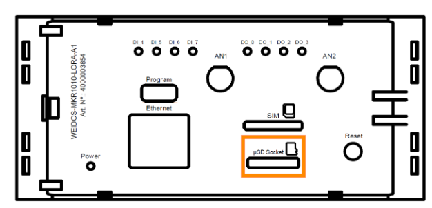
The WIS-PLC incorporates an SD card slot with the following specifications:
- MicroSD slot.
- Up to 32GB of storage (although higher capacity cards can be used, only the first 32GB will be accessible and usable).
- FAT32 and FAT16 allowed as file system architectures.
The SD slot communicates with the WIS-PLC using SPI, and there is no hardware configuration needed. Remember to power the PLC with a proper 12-24Vdc power supply.
The SD slot can be found on the upper plate of the WIS-PLC:
Softwares setup
The industrialshields-wis-esp32/samd boards package includes an SD library to facilitate its usage. Check the following example, which initializes the SD card and prints the contents of its root directory through the serial port.
#include <SD.h>
Sd2Card card;
SdVolume volume;
SdFile root;
void setup() {Serial.begin(115200);
while (!Serial){}delay(5000);
Serial.print("\nInitializing SD card..."); if (!card.init(SPI_QUARTER_SPEED)) { Serial.println("initialization failed. Things to check:"); Serial.println("* is a card inserted?"); Serial.println("* is your wiring correct?"); Serial.println("* did you change the chipSelect pin to match your shield or module?");while (1);
} else { Serial.println("Wiring is correct and a card is present.");}
Serial.println();
Serial.print("Card type: "); switch (card.type()) {case SD_CARD_TYPE_SD1:
Serial.println("SD1");break;
case SD_CARD_TYPE_SD2:
Serial.println("SD2");break;
case SD_CARD_TYPE_SDHC:
Serial.println("SDHC");break;
default:
Serial.println("Unknown");}
if (!volume.init(card)) { Serial.println("Could not find FAT16/FAT32 partition.\nMake sure you've formatted the card");while (1);
}
Serial.print("Clusters: ");Serial.println(volume.clusterCount());
Serial.print("Blocks x Cluster: ");Serial.println(volume.blocksPerCluster());
Serial.print("Total Blocks: ");Serial.println(volume.blocksPerCluster() * volume.clusterCount());
Serial.println();
uint32_t volumesize;
Serial.print("Volume type is: FAT");Serial.println(volume.fatType(), DEC);
volumesize = volume.blocksPerCluster();
volumesize *= volume.clusterCount();
volumesize /= 2;
Serial.print("Volume size (Kb): ");Serial.println(volumesize);
Serial.print("Volume size (Mb): ");volumesize /= 1024;
Serial.println(volumesize);
Serial.print("Volume size (Gb): ");Serial.println((float)volumesize / 1024.0);
Serial.println("\nFiles found on the card (name, date and size in bytes): ");root.openRoot(volume);
root.ls(LS_R | LS_DATE | LS_SIZE);
}
void loop() { Serial.println("SD Info example has ended!"); Serial.print("If you have not seen the result printed in the Serial Monitor "); Serial.println("run again the example and open the Serial Monitor within 5 seconds after the reset.");delay(3000);
}
Multifunction Pins
The multi-function pins accept different operational modes. They can be used as Digital Inputs, Digital Outputs, Interrups or PWM signals (defined via Software PIN MODE).
MF pins can only operate at 3.3Vdc or 5Vdc (configurable by switch). It is very important to check the configuration of the switches for the use of the multi-function pins before making the connection to verify the voltage in which they are configured.
Please check the following table to select the desired signal voltage level:

As described in the table above, only DIP-Switches 1, 2 and 3 from SW1, need to be configured for operational voltage of multi-function pins selection. If they are all in the ON position, the pins will operate at 3,3 Vdc, while if all switches are in the OFF position, they will operate at 5 Vdc.
Multifunction pins are located in the following Weidos connector:

Softwares setup
The industrialshields-wis-esp32/samd boards package includes examples to facilitate its usage. Check the following example, which initializes the two multifunction pins as digital outputs:
void setup(){Serial.begin(115200);
pinMode(pin41, OUTPUT);
pinMode(pin42, OUTPUT);
}
void loop() {//Turn on LED's using connector pin number (pinXX)
digitalWrite((pin41), HIGH);
delay(2000);
digitalWrite((pin42), HIGH);
delay(2000);
//Turn off LED's using WIS pin names (DO_X)
digitalWrite((MF_0), LOW);
delay(2000);
digitalWrite((MF_1), LOW);
delay(2000);
}