Technical Features
M-Duino PLC Family
Initial installation
Arduino IDE
Arduino IDE is the original platform to program Arduino boards. This cross-platform application is available on Windows, macOS and Linux under the GNU General Public License. Arduino IDE supports C and C++ code structuring. In order to program the Arduino Mega based PLCs in this environment, Industrial Shields provides a boards package with the necessary libraries and tools.
We recommend using the Legacy Arduino IDE (2.3.X) to program M-Duino based PLCs, although other Arduino compatible software could be used. The Arduino 2.3.X IDE can be downloaded from this link. After downloading and installing the Arduino IDE, install the industrialshields boards package inside the IDE. This can be done by following this tutorial and selecting the industrialshields package in step number 6.
Power supply
The M-Duino based PLCs need to be powered with an external power supply, providing a voltage between 12 and 24Vdc. Caution! Although at first glance it may seem like the PLC works when powered with the USB port, this is not the case. The usage of an external power supply is mandatory for the PLC to perform properly.
The consumption of M-Duino based PLCs range between 700 and 1500mA. Therefore, Industrial Shields recommends using a power supply capable of delivering at least 2A.
PSU specifications:
- Voltage: between 12 and 24Vdc.
- Intensity: at least 2A.
The diagram in this section illustrates the necessary connections to properly power a PLC.

DIP Switches
The M-Duino based PLCs have some switches which can be used to configure certain functionalities of the PLC. This section explains how to use them properly. To differentiate between the different parts of the PLC and locate every switch accordingly, the following nomenclature will be used:
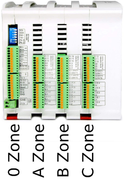
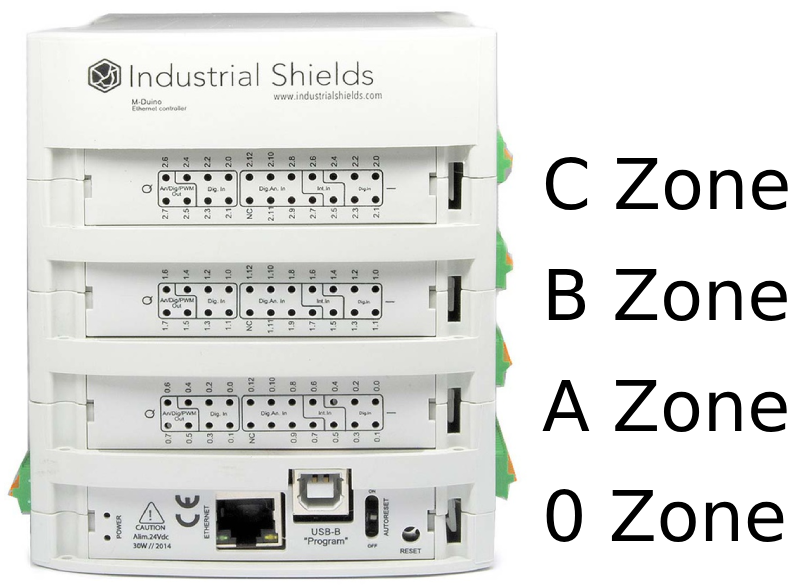
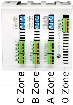
In each zone there are one or more switches, used to configure some of the PLC functionalities. The following tables indicate the purpose of each switch and how to configure them.
A zone: top left switch

Switch | Off | On |
1 (top) | TX1 | I1.X |
2 (top) | RX2 | I1.X |
3 (top) | SDA | I2.X |
4 (top) | SCL | I2.X |
1 (bottom) | FD | HD |
2 (bottom) | SD | X |
3 (bottom) | Pin 2 | I0.X |
4 (bottom) | Pin 3 | I0.X |
Top switch:
- If this switch is ON, it enables the I1.X input and disables TX1. If this switch is OFF, it enables TX1 and disables I1.X.
- If this switch is ON, it enables the I1.X input and disables RX1. If this switch is OFF, it enables RX1 and disables I1.X.
- If this switch is ON, it enables the I2.X input and disables SDA. If this switch is OFF, it enables SDA and disables I2.X.
- If this switch is ON, it enables the I2.X input and disables SCL. If this switch is OFF, it enables SCL and disables I2.X.
Bottom switch:
- If this switch is ON, it enables the Half Duplex (HD) option and disables the FD. If this switch is OFF, it enables Full Duplex (FD) and disables HD.
- If this switch is OFF, it enables the Chip Select of the microSD card. In some M-Duino PLC models, if this switch is ON it enables a digital output.
- If this switch is ON, it enables the I0.X input and disables the Pin 3. If this switch is OFF, it enables Pin 3 and disables I0.X.
- If this switch is ON, it enables the I0.X input and disables the Pin 2. If this switch is OFF, it enables Pin 3 and disables I0.X.
*The X represents different pins for the different M-Duino PLC models.
A zone: bottom left switch

Switch | Off | On |
1 | X | RTC |
2 | X | RTC |
3 | X | X |
4 | X | X |
Only switches 1 and 2 are used. Both switches enable the communication to communicate with the RTC using I2C. Having these switches in ON mode it actives this communication, whereas if it is in
OFF mode it disables the I2C to reach the RTC.
B, C and D Zone: Analog switch

Switch | Off | On |
1 | AX.5 | QX.5 |
2 | AX.6 | QX.6 |
3 | AX.7 | QX.7 |
4 | X | X |
These switches are used to choose between digital or analog output, according to the previous table. If it is set to OFF, only the corresponding analog output will be available. If it is set to ON, only the corresponding digital output will be available. The switches behave the same way in zones B, C and D, with the "X" value being different depending on the zone:
- Zone B: X = 0
- Zone C: X = 1
- Zone D: X = 2
Power consumption
This report explores how different M-Duino PLC models consume power
during idle and high-output scenarios. Understanding these patterns is
crucial for optimizing efficiency in industrial applications.
Resting
In this scenario, the M-Duino PLC is powered on, with all pins and communications turned off and utilizing a 24V power supply. This test measures the baseline power consumption when the device is idle and not actively engaged in any processing or output tasks.
MODEL | CURRENT (mA) | POWER (W) |
| 21+ | 99 | 2,376 |
| 42+ | 92 | 2,208 |
| 58+ | 76 | 1,824 |
| 19R+ | 80 | 1,92 |
| 38R+ | 77 | 1,848 |
| 57R+ | 73 | 1,752 |
| 38AR+ | 72 | 1,728 |
| 53ARR+ | 71 | 1,704 |
| 57AAR+ | 71 | 1,704 |
| 54ARA+ | 76 | 1,824 |
| 50RRA+ | 82 | 1,968 |
All outputs HIGH
For this test, the M-Duino PLC is configured to set all its output pins to a high state, drawing the maximum current for output operations and utilizing a 24V power supply. This provides insights into the power consumption when the device is actively driving output signals.
MODEL | CURRENT (mA) | POWER (W) |
| 21+ | 120 | 2,88 |
| 42+ | 128 | 3,072 |
| 58+ | 126 | 3,024 |
| 19R+ | 202 | 4,848 |
| 38R+ | 313 | 7,512 |
| 57R+ | 425 | 10,2 |
| 38AR+ | 221 | 5,304 |
| 53ARR+ | 323 | 7,752 |
| 57AAR+ | 221 | 5,304 |
| 54ARA+ | 231 | 5,544 |
| 50RRA+ | 322 | 7,728 |
Inputs & Outputs
Analog inputs
Analog input provides a way to read analog voltage levels, coding the value with an N-bit number. The analog inputs on the M-Duino based PLC use the internal GND for reference (the same as the power supply). The analog inputs on these PLCs have the following specifications:
- Voltage range: from 0 to 10 Vc.
- Resolution: 10 bits, which means the read values can range between 0 and 1023.
Additionally, the analog inputs can also be used as non isolated digital inputs tolerating up to 24Vdc. To do so, refer to the digital inputs section. The analog inputs are the ones between IX.7 and IX.12, with X being 0, 1 or 2 depending on the zone. You can identify the analog inputs on your device with the following symbol:

0V - 10Vdc Analog input
The next diagram illustrates the necessary connections to properly use an analog input (when used as a digital, the input can tolerate up to 24V):

Software setup
In order to use them, the analog inputs must be configured in the set up part of the code, like it is usually done in common Arduino boards. Then they can be read using the "analogRead()" function, with the input name as its parameter. For example, I0.7 is read as I0_7:
The following post might also be of interest: Learning the basics about analog inputs of an industrial PLC.
Digital inputs
Digital inputs are used to capture signals that exist in one of two states: high or low, true or false, etc. The M-Duino PLC digital inputs interpret as high values of 5 Vdc or higher, up to 24 Vdc, whereas values lower than 5V are interpreted as low. There are 2 types of inputs which can be used as digital input:
- Digital isolated inputs (5 - 24 Vdc): these inputs are opto-isolated, which means they have an extra protection and they use an external ground pin for reference. They are the pins from IX.0 to IX.6, where X is 0,1 or 2 depending on the zone.
- Digital non-isolated input (5 - 24 Vdc): these inputs are not opto-isolated, and they use the internal GND of the PLC as reference. They are the same as the analog inputs, going from IX.7 to IX.12, with X being 0, 1 or 2 depending on the zone.
You can identify them with the following symbols:

5V - 24V isolated input

5V - 24V non-isolated input
The next diagrams illustrate the necessary connections to properly use both inputs as digital:


Software setup
In order to use them, the digital inputs must be configured in the set up part of the code, like it is usually done in common Arduino boards. Then they can be read using the "digitalRead()" function, with the input name as its parameter. For example, I0.0 is read as I0_0:
The following posts expand on this topic: Basics about digital inputs of an industrial controller, PNP Digital Inputs on industrial PLC.
Interrupt Inputs
Some of the digital inputs in the M-Duino PLC are interrupt capable, which means they can be used with ISRs (interrupt service routine) to trigger certain code execution when an event (a change of state in the pin) is detected. There are two pins of this type each zone: IX.5 and IX.6. They are used and connected as regular digital isolated inputs, and the interrupts are programmed through software.
Hardware setup
The interrupt inputs need to be activated using the A zone top switches:
- I0.5 and I0.6 also work as Pin3 and Pin2. Enable Interrupts turning ON the switches number 3 and 4 of down communication switches.
- I1.5 and I1.6 also work as Tx1 and Rx1. Enable Interrupts turning ON the switches number 1 and 2 of up communication switches.
- I2.0 and I2.1 also work as SCA and SCL. Enable Interrupts turning ON the switches number 3 and 4 of up communication switches. In this case you won’t be able to use I2C.
Check the "Initial installation - Hardware" section in this page for more information.
Software setup
This is an example of how to use the interrupt pins. In this case, the function "isrI0_5()" is automatically called every time a change of state occurs on the I0.5 pin.
Analog Outputs
An analog output provides a voltage determined by a digital value with an N-bit number. The M-Duino PLCs can have between 3 and 9 analog outputs, depending on the model. These are labeled as AX.X, and need to be selected via DIP switch to be used. Refer to the switch section in this page for more information about the switches. The analog outputs in the M-Duino PLC have the following specifications:
- Voltage range: from 0 to 10 Vac.
- Resolution: 8 bits.
The analog outputs have a shared external GND pin, which needs to be connected to set the reference. This symbol identifies the analog outputs, and the following diagram illustrates how to connect:
 0 - 10V analog output

Software setup
The procedure to program the analog outputs is the same as regular Arduino: first, the pin mode must be set to "OUTPUT" in the setup of the code, and then the output can be written using "analogWrite()". The analog outputs can be referenced by its name and using a "_" instead of the ".". For example, A0.5 is used as A0_5:
To know more about analog outputs: Basics about analog outputs of an industrial PLC.
Digital outputs
The M-Duino PLC digital outputs can provide a low (0 Vdc) or high (up to 24 Vdc) value. These outputs are labeled as QX.X, and can be identified with the next symbol.
The output high value can range between 5 and 24 Vdc. This voltage needs to be set using two pins located next to the outputs: QVdc and COM(-). For instance, should you wanna set the output to 24V, the QVdc pin should be connected to 24V and the COM(-) pin to GND. The following diagram illustrates an example connection:
")
Digital output (PWM optional)

Software setup
The digital outputs must be configured in the setup part of the code like it is usually done in common Arduino boards, using the "pinMode()" first to set it as "OUTPUT", and "digitalWrite()" to change the output value. Check the following example:
You can learn more about digital outputs in this post: Basics about digital outputs of an industrial PLC.
PWM output
In the M-Duino based PLCs, some of the digital outputs can be used as PWM outputs.
The output high value can range between 5 and 24 Vdc. As when using them as simple digital outputs, this voltage needs to be set using two pins located next to the outputs: QVdc and COM(-). For instance, if you want to set the output to 24V, the QVdc pin should be connected to 24V and the COM(-) pin to GND. The following diagram illustrates an example connection.
An example tutorial about how to program the PLC to use the PWM outputs can be found in our repository using the avr-Pulses library.
PWM capable output

Relay output
A relay is an electromagnetic switch controlled by an electric signal. In Industrial Shields units these devices are already integrated in their boards. The relays included in the M-Duino PLC can work up to 24 Vdc or 220 Vac. Each relay output has two terminals, and is labelled as RX. The following diagram illustrates the connections:

Software setup
The relay output must be configured in the set up part of the code, using Arduino functions, and they are controlled as if they were digital outputs. The outputs can be referenced by the name shown in the serigraphy: R0.1 for instance is used as R0_1. Check the following example. When the output is set to "HIGH", the real i turned on, meaning the switch closes, whereas when it is set to "LOW" the switch is open.
To know more about the relay outputs, check out this post: Learning the basics about internal relays of an industrial PLC.
Communications
Ethernet
Ethernet is the most commonly used technology in wired local area networks ( LANs ).
A LAN is a network of computers and other electronic devices that covers a small area such as a room, office, or building. It is used in contrast to a wide area network (WAN) , which spans much larger geographical areas. Ethernet is a network protocol that controls how data is transmitted over a LAN. Technically it is referred to as the IEEE 802.3 protocol. The protocol has evolved and improved over time to transfer data at the speed of a gigabit per second.
The M-Duinos PLCs incorporate an Ethernet port, using the W5500 controller, which communicates with the Arduino using SPI. The W5500 is a Hardwired TCP/IP embedded Ethernet controller that provides easier Internet connection to embedded systems. This chip enables users to have Internet connectivity in their applications by using the single chip in which TCP/IP stack, 10/100 Ethernet MAC and PHY are embedded. With this chip users can integrate Ethernet into their applications.
Software setup
The Industrial Shields boards package includes an "Ethernet" library, intended to facilitate the use of this protocol. Various examples are included with the library, you can check them out going to File > Examples > Ethernet inside the Arduino IDE.
Also take a look at the following program. Before running the code, ensure that your PLC is powered correctly, confirm that the Ethernet cable is securely connected to your device and make sure the "industrialshields" board package is properly installed in your Arduino IDE. This code serves as a diagnostic tool to ensure the proper functioning of the Ethernet port. It establishes a connection to "www.google.com" through the W5500 controller using DHCP IP configuration.
RS-485
RS485, also known as TIA-485(-A), EIA-485, is a standard defining the electrical characteristics of drivers and receivers for use in serial communications systems.The M-Duino PLCs include half-duplex RS485 capabilites, thanks to the incorporated MAX485 transceiver chip.
The MAX485 is a low-power and slew-rate-limited transceiver used for RS-485 communication. It works at a single +5V power supply and the rated current is 300 μA. Adopting half-duplex communication to implement the function of converting TTL level into RS-485 level, it can achieve a maximum transmission rate of 2.5Mbps. MAX485 transceiver draws supply current of between 120μA and 500μA under the unloaded or fully loaded conditions when the driver is disabled.
If you want to know more about RS485, check out this post.
Hardware setup
In order to use the RS485 with the M-Duino PLCs, check the A zone top left switch. The RS485 is always active, but there is a switch (number 1) used to choose between half-duplex and full-duplex. For more information about the switches, check the "Initial installation - Hardware" section in this page.
The RS485 pins, A+ and B- need to be properly connected to the device the PLC is communicating with. Attention! Remember to properly power the PLC with a 12-24V power supply.
Software setup
Our boards package includes an RS485 library to make programming easier. This library is used as the Arduino Serial library, with methods such as "available()", "read()", etc.
Check out the following code, which establishes half duplex communication and allows the user to read or send messages from the terminal of the PC.
RS232
RS-232 is a standard for serial communication transmission of data. It formally defines the signals used in communication between DTE (Data Terminal Equipment) such as a computer terminal, and DCE (Data Circuit-terminating Equipment or Data Communication Equipment), such as a modem. The M-Duino PLC includes a MAX232 transceiver chip, allowing full-duplex communication through RS232. The MAX232 is a dual transmitter/dual receiver that is used to convert the RX, TX, CTS, RTS signals, converting signals from Serial TTL to TIA-232 (RS-232) serial port.
If you want to know more about RS232, check this post.
Hardware setup
The RS232 pins, TX and RX need to be properly connected to the device the PLC is communicating with. Attention! Remember to properly power the PLC with a 12-24V power supply.
Software setup
Once the hardware configuration is done, it is possible to proceed with the software configuration and its usage. Firstly, it is necessary to include the RS232.h library provided by our boards package. Then, the communication must be initialized with "RS232.begin(<baudrate>);". After this RS232 can already be used with the functions "RS232.read();" and "RS232.write();".
Check the following read and write examples:
Serial TTL
Serial TTL is a communication Interface between two devices with working at a low level voltage. Two signals are used: Tx (Transmit Data) and Rx (Receive Data), which allow full-duplex communication. The M-Duino PLCs have two external TTL ports, Serial 1 (RX1/TX1) and Serial 0 (RX0/TX0).
To know more about the serial TTL interface, visit this blog.
Hardware setup
The M-Duino PLC features two serial ports. One of them, the Serial 1 (TX1, RX1), needs to be activated using the A zone top left switch. For more information about the switches, check the "Initial installation - Hardware" section in this page.
For the Serial communication to work, the following connections between the PLC and the other device need to be made:
- TX -> RX
- RX -> TX
- GND, both devices need to share a common ground.
Attention! The M-Duino PLCs serial ports work at 5V levels. Higher voltage levels might damage the PLC.
Also, remember to properly power the PLC with a suitable 12-24Vdc power supply.
Software setup
In order to use the Serial communication with the PLC, the Arduino "Serial" object can be used. Check the following example, which uses Serial 1, to send and receive byte using the USB serial port and the Serial 1. To use the Serial 2 instead of the 1, the "Serial2" object must be used.
I2C
I2C is a serial communications protocol. It is a master-slave synchronous protocol and 2 cables are used, one for the clock (SCL) and one for the data (SDA).
The master controls the bus and creates the clock signal, and uses addressing to communicate with the slaves. It is a very used bus in the industry, mainly to
communicate microcontrollers and their peripherals in integrated
systems, normally located in the same PCB. The speed is 100 Kbit/s in standard mode.
Hardware setup
The M-Duino PLCs have one I2C port, with the SCL and SDA pins. These pins need to be activated using the A zone top left switch (SCL and SDA need to be selected in switches 3 and 4). For more information about the switches, check the "Initial installation - Hardware" section in this page.
Other devices can be connected to this bus as slaves. When connecting other devices, keep in mind the following specifications:
- The I2C port works at 5V. Higher voltage levels might damage the PLC.
- The I2C pins, SCL and SDA, are pulled up to 5V.
Also, remember to properly power the PLC with a suitable 12-24Vdc power supply.
Software Setup
The I2C can be used with the library "Wire". Check the following example which implements an I2C scanner that searches the bus for any connected devices. When a device is detected, it will be reported to the serial monitor. Note that if you connect the I2C pins (SDA and SCL) to an other device, it should appear in the scan.
Before running the code, ensure that your PLC is powered correctly, verify that the "industrialshields" board package is correctly installed in your Arduino IDE and that you have selected the correct PLC model inside your IDE.
SPI
The Serial Peripheral Interface (SPI) is a synchronous serial communication interface specification used for short-distance communication, primarily in embedded systems. SPI devices communicate in full duplex mode using a master-slave architecture, usually with a single master. 3 pins are used with SPI communication: SCLK, MOSI, MISO. Additionally, one extra pin for each slave, called chip select (CS) or slave select (SS) is used to select the slave that is being talked to in the bus.
The M-Duino PLC features one SPI port.
Hardware setup
In order to use the SPI, the 3 mention pins (SCLK, MISO, MOSI) must be properly connected:
Function | M-Duino PLC Pin | Arduino Mega Pin |
MISO | SO | 50 |
MOSI | SI | 51 |
CLOCK | SCK | 52 |
RST | Reset | Reset |
Attention! The SPI works at 5V voltage levels, any higher voltage might damage the PLC.
Also, remember to properly power the PLC with a suitable 12-24Vdc power supply.
Software setup
The "industrialshields" boards package includes an SPI library, based on the Arduino SPI library. This library allows programming the MDuino as an SPI master.
This program shows how to set up the MDuino
as a master in SPI communication, and send and receive data. In this
case the character "0" is sent, and the received data is stored in the
corresponding variable (SPI transfer is based on a simultaneous send and
receive) and printed through the serial port.
To know more about SPI check the following post: Bus SPI on PLC Arduino from Industrial Shields
Extra features
RTC
RTC stands for Real Time clock, en electronic device that measures the passage of time. Although keeping time can be done without an RTC, using one has benefits such as:
- Mantaining the time without needing to set ti again after a reboot, shutdown, etc.
- Low power consumption (important when running from alternate power.
- Frees the main control system for time-critical tasks.
- Sometimes more accurate than other methods.
The M-Duino PLC include a DS1307 RTC module, which communicates with the Arduino microcontroller using I2C. The DS1307 serial real-time clock is a lowpower, full binary-coded decimal (BCD) clock/calendar, including 56 bytes of NV SRAM. Iprovides seconds, minutes, hours, day, date, month, and year information.
In order to power the RTC when the PLC is not connected, the PLC includes a 3,3V lithium coin cell battery which can be used to supply the RTC.
No hardware setup is needed in order to use the RTC, the only requirement is for the PLC to be properly powered using a 12-24Vdc power supply, and to have a lithium coin cell battery to maintain the time when the PLC has no power.
Software setup
The RTC library, included with our boards package, can be used to interact with the RTC. Check the following code example where time is read from the RTC and printed to the serial monitor.
Remember to make sure you have the industrialshields board package properly installed in your Arduino IDE.
SD
Secure Digital (SD) cards are non-volatile memory storage devices that
use flash memory technology. Designed for portable electronic devices,
SD cards provide a reliable and compact solution for data storage.
The M-Duino PLC incorporates an SD card slot with the following specifications:
- MicroSD slot.
- Up to 32GB of storage (although higher capacity cards can be used, only the first 32GB will be accessible and usable).
- FAT32 and FAT16 allowed as file system architectures.
The SD slot communicates with the M-Duino using SPI, and there is no hardware configuration needed. Remember to power the PLC with a proper 12-24Vdc power supply.
Hardware setup
In order to use the SD with the M-Duino PLCs, check the A zone top left
switch. For more information about the switches, check the "Initial
installation - Hardware" section in this page.
Software setup
The "industrialshields" boards package includes an SD library to facilitate its usage. Check the following example, which initializes the SD card and prints the contents of it root directory through the serial port.
Direct Arduino Pins
If we want to use another Serial Port using this equipment, we can make use of some digital pins to create a Serial. The SoftwareSerial library has been developed to allow serial communication on other digital pins of the Arduino, using software to replicate the functionality. It is possible to have multiple software serial ports with speeds up to 115200 bps. A parameter enables inverted signaling for devices which require that protocol.
Only I/O 5V from Ardbox or M-Duino boards can be used.
| M-Duino Pins | Ardino Mega Pins |
| MISO | 50 |
| MOSI | 51 |
| SCK | 52 |
5 Vdc Signals
These pins can be programmed according to Arduino features such as I/Os operating at 5V or any additional features present in the pins.
- I2C Pins – SDA/SCL: The I2C protocol is meant to work in a pull-up configuration. In this case it reads 5V when nothing is connected.
- Serial 0 – RX0/TX0: The Serial0 protocol can work also as a 5V pin. If using these pins, the USB communication cannot be working at the same time.
- Serial 1 – RX1/TX1: The Serial1 protocol can work also as a 5V pin. Always enabled.
- SPI – MISO/MOSI/SCK: These pins can only work as a 5V pins if the Ethernet protocol is not going to be used. As the Ethernet protocol uses the SPI to communicate with the
Arduino board, both behaviors cannot happen at the same time as the Ethernet would not work. - Pin2/Pin3: These pins are only referred to the inputs I0.5/I0.6. If the switch configuration is in OFF position the pins Pin 2/Pin 3 will be available.