ANALOG INPUTS
Understand the Analog Inputs of Industrial Arduino Controllers
Learn how to connect this inputs and make it work
Voltage variation between –Vcc (or GND) and +Vcc, can take any value. An analog input provides a coded measurement in the form of a digital value with an N-bit number.
In Digital and Analog I/O there’s self insulation, so its posible to connect them in a different power supply than 24 V.
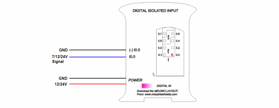
Typical Connection
DIGITAL INPUTS
Digital Inputs of Industrial Controllers
Understand the digital inputs of the Open Source based PLC
Voltage variation from –Vcc (or GND) to +Vcc, with no intermediate values. Two states: 0 (-Vcc or GND) and 1 (+Vcc).
In Digital and Analog I/O there’s self insulation, so its posible to connect them in a different power supply than 24 V.
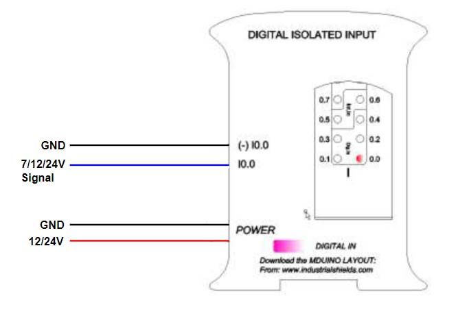
Digital Isolated Input
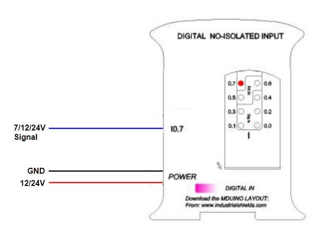
Digital No Isolated Input
INTERRUPT INPUTS
Interrupt Inputs of Open Source based PLC
Understand the digital inputs of the Open Source based PLC
What is an Interrupt Service Routine?
A mechanism that allows a function to be associated with the occurrence of a particular event. When the event occurs the processor exits immediately from the normal flow of the program and runs the associated ISR function ignoring any other task.
|
Interrupt
|
Arduino Mega Pin
|
M-Duino Pin
|
|
INT0
|
2 |
I0.5/INT0
|
|
INT1
|
3 |
I0.6/INT1
|
|
INT4
|
19 |
I1.6/INT4
|
|
INT5
|
18 |
I1.5/INT5
|
|
INT2
|
21 |
I2.6/INT2
|
|
INT3
|
20 |
I2.5/INT3
|
- I0.5/INT0 and I0.6/INT1 also as Pin3 and Pin2. Enable Interrupts turning ON the switches number 3 and 4 of down communication switches.
- I1.5/INT4 and I1.6/INT5 also as Tx1 and Rx1. Enable Interrupts turning ON the switches number 1 and 2 of up communication switches.
- I2.5/INT3 and I2.6/INT2 also as SCA and SCL. Enable Interrupts turning ON the switches number 3 and 4 of up communication switches. In this case you won’t be able to use I2C.
Digital Isolated Input
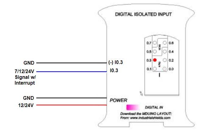
In this code example we activate INT0 using pin I0_5 from M-Duino board.
#define INTERRUPT I0_5 //other pins: I0_6, I2_6, I2_5, I1_6, I1_5 (M-Duino) I0_0, I0_3, I0_2, I0_1 (Ardbox)

volatile bool state = false;

void setup() {
  pinMode(INTERRUPT, INPUT_PULLUP);
  attachInterrupt(digitalPinToInterrupt(INTERRUPT), function_call_back, CHANGE);
}

void loop() {
  if (state == true){
    Serial.println("Interrupt activated");
    state = false;
  }
}

void function_call_back(){ //Change led state
  state = true;
}
Inputs and Outputs in detail
Download the Guide with all kinds of analog, digital, interrupt and PWM inputs and outputs
If you want to know everything about inputs, outputs and the detail of Analog, Digital, Interrupt or PWM, you can download this Guide.