

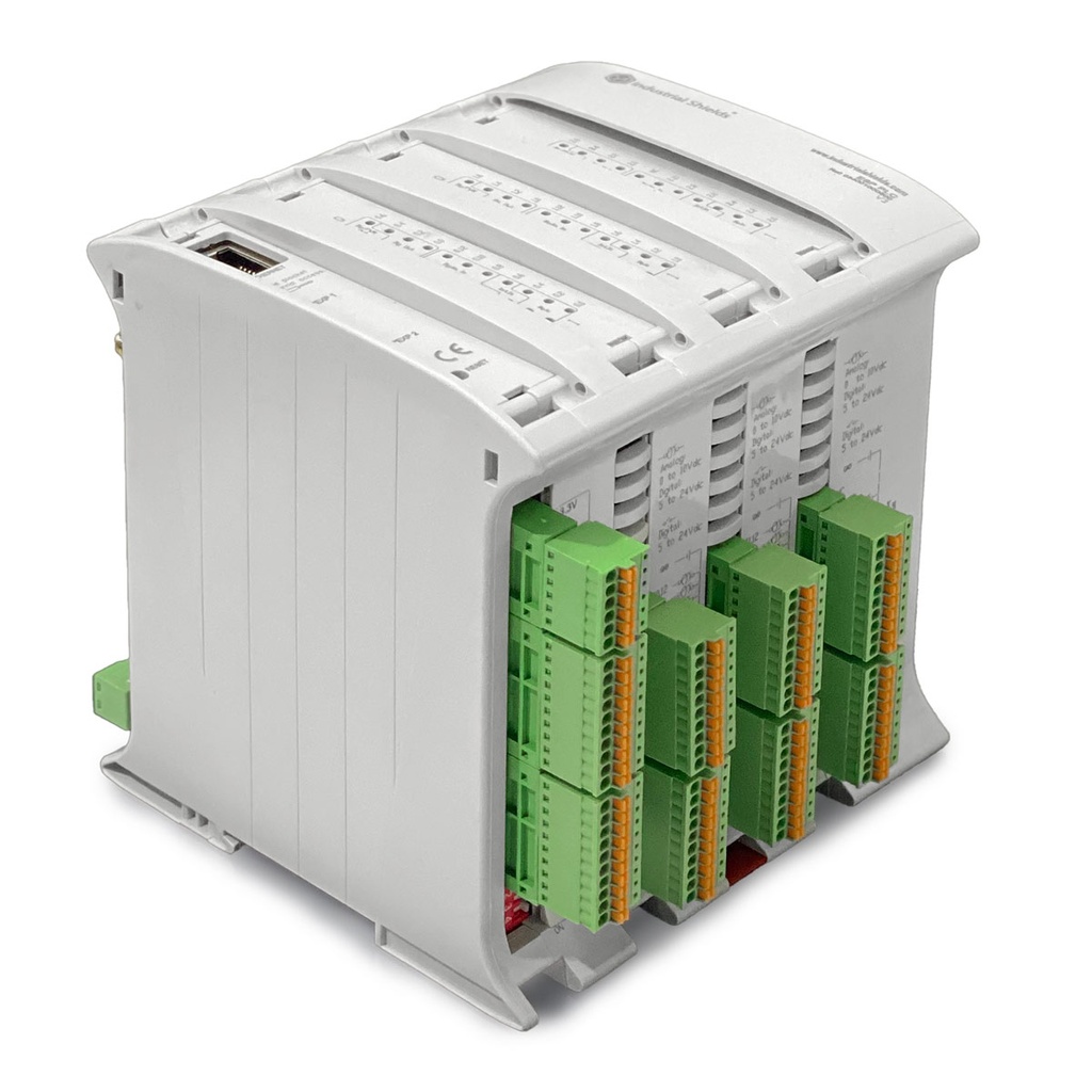


ESP32 PLC 58: 39 E/S con Analógicas, Digitales y WiFi/BLE Integrado
El ESP32 PLC 58 es el controlador de mayor densidad de la familia ESP32 PLC, basado en el microprocesador Espressif ESP32 de doble núcleo (240 MHz) con WiFi 802.11 b/g/n y Bluetooth 4.2 / BLE integrados. Combina 18 entradas analógicas/digitales convertibles (0-10 Vdc), 21 entradas digitales optoacopladas (6 con capacidad de interrupción), 15 salidas digitales y 9 salidas digitales/PWM/analógicas en una unidad en carril DIN, totalmente programable con Arduino IDE. Disponible con placas de comunicación opcionales LoRa, CAN o 4G.
Especificaciones técnicas
| Especificación | Valor |
|---|---|
| Microcontrolador | ESP32 dual-core Tensilica LX6, 240 MHz |
| Entradas analógicas/digitales convertibles (0-10 Vcc) | 18 |
| Entradas digitales aisladas (5-24 Vcc) | 21 (6 con interrupción) |
| Salidas digitales (5-24 Vcc) | 15 |
| Salidas digitales / PWM / analógicas (0-10 Vcc) | 9 |
| Salidas de relé | 0 |
| Ethernet | Sí |
| WiFi | 802.11 b/g/n 2.4 GHz (integrado) |
| Bluetooth / BLE | Bluetooth 4.2 / BLE (integrado) |
| Puertos RS-485 | 2 |
| Puertos RS-232 | 1 |
| TTL Serie / UART | 2 |
| SPI | Sí |
| I2C | Sí |
| RTC | Sí |
| Ranura MicroSD | Sí |
| Alimentación | 12-24 Vdc |
| Consumo máximo de potencia | 2.88 W (1.85 W en reposo) |
| Montaje | Carril DIN |
| Certificaciones | CE, RoHS, UKCA |
Configuraciones disponibles
| Referencia | Configuración |
|---|---|
| 034001000600 | ESP32 PLC 58 — Estándar |
| 034001100600 | ESP32 PLC 58 + CAN |
| 034001200600 | ESP32 PLC 58 + LoRa (Europa — EU868) |
| 034001200600 (Asia) | ESP32 PLC 58 + LoRa (Asia — EU443) |
| 034001300600 | ESP32 PLC 58 + 4G (M1)-NB1 IoT LTE |
| 034001600600 | ESP32 PLC 58 + LoRa (EE. UU. — US902) |
Aplicaciones: IIoT, Smart Cities y monitorización remota
The ESP32 PLC 58 is designed for applications that combine dense I/O with built-in wireless connectivity. Its 39 I/Os and WiFi make it ideal for IIoT gateways, SCADA front-ends, smart building automation, remote monitoring and energy management. It has been deployed in public lighting networks managing over 300,000 luminaires in smart city projects, in industrial bottling line digitalization and in wood research automation. See also: cloud control with Arduino Cloud, local SQLite data logging, power metering. More examples in the Solution Library.
Protocolos: MQTT, Modbus, Profinet, LoRa, CAN, 4G
The built-in WiFi stack (2.4 GHz and 5 GHz) supports MQTT with TLS, HTTP and Modbus TCP. RS-485 supports Modbus RTU and the Profinet protocol for Siemens S7 integration. RS-232 covers legacy equipment. Optional communication boards add LoRa / LoRaWAN, CAN bus, and 4G LTE / NB-IoT. Additional buses: 1-Wire, I2C, SPI and Serial TTL.
Programación: Arduino IDE, PlatformIO y OpenPLC
Get started with the industrialshields-esp32 board package for Arduino IDE — all I/Os are addressed by name (I0_7, A0_5, Q0_0) with no pin mapping required. Prefer VS Code? The PlatformIO extension supports the same workflow. The dual-core architecture enables FreeRTOS multitasking across both cores. Update firmware over the air (OTA) via WiFi. For IEC 61131-3 programming (Ladder, Structured Text), OpenPLC is supported.
Entradas y Salidas
Analog inputs
La entrada analógica proporciona una forma de leer los niveles de tensión analógica, codificando el valor con un número de N bits. Las entradas analógicas en el PLC basado en ESP32 utilizan el GND interno como referencia (el mismo que la fuente de alimentación). Las entradas analógicas en estos PLC tienen las siguientes especificaciones:
- Rango de voltaje: de 0 a 10 Vdc.
- Resolution: 11 bits, which means the read values can range between 0 and 2047.
Además, las entradas analógicas también pueden utilizarse como entradas digitales no aisladas que toleran hasta 24Vdc. Para ello, consulte el apartado de entradas digitales. Las entradas analógicas son las comprendidas entre IX.7 y IX.12, siendo X 0, 1 o 2 según la zona. Puede identificar las entradas analógicas de su equipo con el siguiente símbolo:
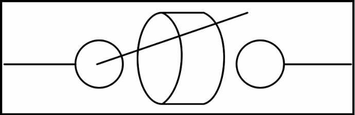
0V - 10Vdc Entrada analógica
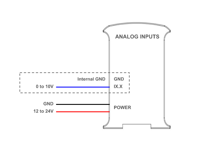
The next diagram illustrates the necessary connections to properly use an analog input (when used as a digital, the input can tolerate up to 24V):
Software setup
In order to use them, the analog inputs must be configured in the set up part of the code, like it is usually done in common Arduino boards. Then they can be read using the "analogRead()" function, with the input name as its parameter. For example, I0.7 is read as I0_7:
The following post might also be of interest: Learning the basics about analog inputs of an industrial PLC.
Entradas digitales
Las entradas digitales se utilizan para capturar señales que existen en uno de dos estados: high o low, verdadero o falso, etc. Las entradas digitales del PLC ESP32 interpretan como altos valores de 5 Vdc o superiores, hasta 24 Vdc, mientras que valores inferiores a 5V se interpretan como bajos. Hay 2 tipos de entradas que se pueden utilizar como entrada digital:
- Digital isolated inputs (5 - 24 Vdc): these inputs are opto-isolated, which means they have an extra protection and they use an external ground pin for reference. They are the pins from IX.0 to IX.6, where X is 0,1 or 2 depending on the zone.
- Entradsa digitales no aisladas (5 - 24 Vdc): estas entradas no están optoaisladas, y utilizan el GND interno del PLC como referencia. Son iguales que las entradas analógicas, van de IX.7 a IX.12, siendo X 0, 1 o 2 según la zona.
Puedes identificarlos con los siguientes símbolos:
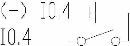
5V - 24V entrada aislada

5V - 24V entrada no aislada
The next diagrams illustrate the necessary connections to properly use both inputs as digital:
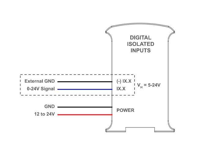
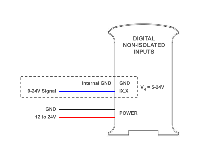
Software setup
In order to use them, the digital inputs must be configured in the set up part of the code, like it is usually done in common Arduino boards. Then they can be read using the "digitalRead()" function, with the input name as its parameter. For example, I0.0 is read as I0_0:
The following posts expand on this topic: Basics about digital inputs of an industrial controller, PNP Digital Inputs on industrial PLC.
Entradas de interrupción
Some of the digital inputs in the ESP32 PLC are interrupt capable, which means they can be used with ISRs (interrupt service routine) to trigger certain code execution when an event (a change of state in the pin) is detected. There are two pins of this type each zone: IX.5 and IX.6. They are used and connected as regular digital isolated inputs, and the interrupts are programmed through software.
Configuración del software
This is an example of how to use the interrupt pins. In this case, the function "isrI0_5()" is automatically called every time a change of state occurs on the I0.5 pin.
To know more about interrupts inputs: How to use Interrupt Inputs with industrial Arduino boards
Salidas analógicas
An analog output provides a voltage determined by a digital value with an N-bit number. The ESP32 PLCs can have between 3 and 9 analog outputs, depending on the model. These are labeled as AX.X, and need to be selected via DIP switch to be used (check the hardware section on this page for more information.). Refer to the switch section in this page for more information about the switches. The analog outputs in the ESP32 PLC have the following specifications:
- Rango de voltaje: de 0 a 10 Vdc.
- Resolución: 12 bits.
The analog outputs have a shared external GND pin, which needs to be connected to set the reference. This symbol identifies the analog outputs, and the following diagram illustrates how to connect:

0 - 10V salida analógica
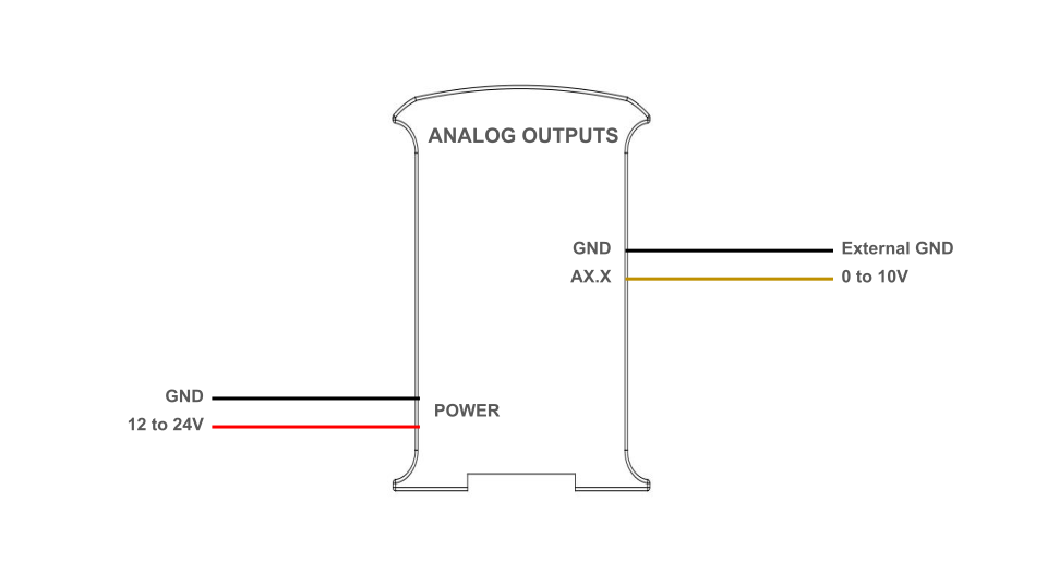 Configuración del software
The procedure to program the analog outputs is the same as regular Arduino: first, the pin mode must be set to "OUTPUT" in the setup of the code, and then the output can be written using "analogWrite()". The analog outputs can be referenced by its name and using a "_" instead of the ".". For example, A0.5 is used as A0_5:
To know more about analog outputs: Basics about analog outputs of an industrial PLC.
Digital outputs
Las salidas digitales del ESP32 pueden proporcionar un valor bajo (0 Vcc) o alto (hasta 24 Vcc). Estas salidas se etiquetan como QX.X, y se pueden identificar con el siguiente símbolo.
The output high value can range between 5 and 24 Vdc. This voltage needs to be set using two pins located next to the outputs: QVdc and COM(-). For instance, should you wanna set the output to 24V, the QVdc pin should be connected to 24V and the COM(-) pin to GND. The following diagram illustrates an example connection:
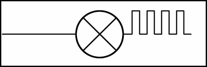
Salida digital (PWM opcional)
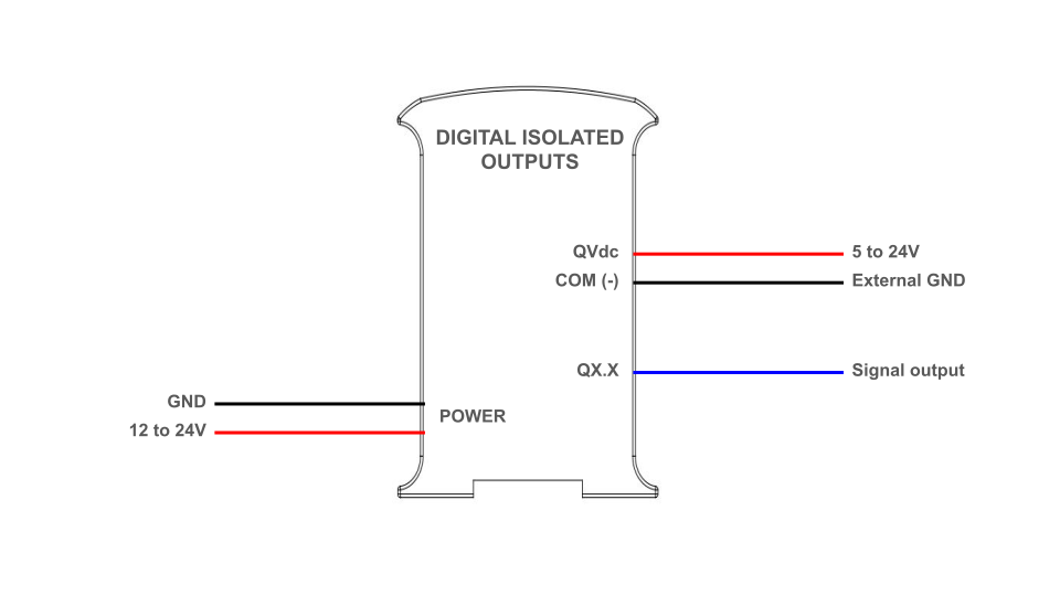
Software setup
The digital outputs must be configured in the setup part of the code like it is usually done in common Arduino boards, using the "pinMode()" first to set it as "OUTPUT", and "digitalWrite()" to change the output value. Check the following example:
You can learn more about digital outputs in this post: Basics about digital outputs of an industrial PLC.
PWM output
In the ESP32 based PLCs, all the digital outputs can be used as PWM outputs.
The output high value can range between 5 and 24 Vdc. As when using them as simple digital outputs, this voltage needs to be set using two pins located next to the outputs: QVdc and COM(-). For instance, should you wanna set the output to 24V, the QVdc pin should be connected to 24V and the COM(-) pin to GND. The following diagram illustrates an example connection.
An example tutorial about how to program the PLC to use the PWM outputs can be found in this website.
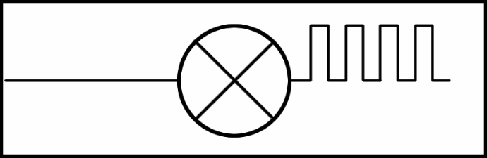
PWM capable output
Salida relé
Un relé es un interruptor electromagnético controlado por una señal eléctrica. En las unidades Industrial Shields estos dispositivos ya están integrados en sus placas. Los relés incluidos en el PLC ESP32 tienen las siguientes especificaciones:
- Corriente continua máxima: 3A a 30Vdc.
- Corriente AC máxima: 5A a 250Vac
Cada salida de relé tiene dos terminales, y está etiquetada como RX.X. El siguiente diagrama ilustra las conexiones:
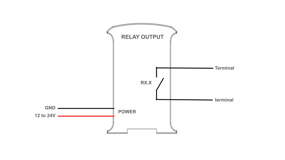
Software setup
The relay output must be configured in the set up part of the code, using Arduino functions, and they are controlled as if they were digital outputs. The outputs can be referenced by the name shown in the serigraphy: R0.1 for instance is used as R0_1. Check the following example. When the output is set to "HIGH", the real i turned on, meaning the switch closes, whereas when it is set to "LOW" the switch is open.
To know more about the relay outputs, check out this post: Learning the basics about internal relays of an industrial PLC.
Comunicaciones
Ethernet
Ethernet is the most commonly used technology in wired local area networks ( LANs ).
A LAN is a network of computers and other electronic devices that covers a small area such as a room, office, or building. It is used in contrast to a wide area network (WAN) , which spans much larger geographical areas. Ethernet is a network protocol that controls how data is transmitted over a LAN. Technically it is referred to as the IEEE 802.3 protocol. The protocol has evolved and improved over time to transfer data at the speed of a gigabit per second.
The ESP32 PLCs incorporate an Ethernet port, using the W5500 controller, which communicates with the ESP32 using SPI. The W5500 is a Hardwired TCP/IP embedded Ethernet controller that provides easier Internet connection to embedded systems. This chip enables users to have Internet connectivity in their applications by using the single chip in which TCP/IP stack, 10/100 Ethernet MAC and PHY are embedded. With this chip users can integrate Ethernet into their applications.
Configuración del software
The Industrial Shields boards package includes an "Ethernet" library, intended to facilitate the use of this protocol. Various examples are included with the library, you can check them out going to File > Examples > Ethernet inside the Arduino IDE.
Also take a look at the following program. Before running the code, ensure that your PLC is powered correctly, confirm that the Ethernet cable is securely connected to your device and make sure the "industrialshields-esp-32" board package is properly installed in your Arduino IDE. This code serves as a diagnostic tool to ensure the proper functioning of the Ethernet port. It establishes a connection to "www.google.com" through the W5500 controller using DHCP IP configuration.
Para saber más sobre la comunicación Ethernet:
RS-485
RS485, también conocido como TIA-485(-A), EIA-485, es un estándar que define las características eléctricas de los controladores y receptores para su uso en sistemas de comunicaciones en serie. El PLC ESP32 incluye capacidades RS485 half-duplex, gracias al chip transceptor MAX485 incorporado.
El MAX485 es un transceptor de baja potencia y slew-rate limitado utilizado para la comunicación RS-485. Funciona con una sola fuente de alimentación de +5 V y la corriente nominal es de 300 μA. Al adoptar la comunicación semidúplex para implementar la función de convertir el nivel TTL en nivel RS-485, puede alcanzar una velocidad de transmisión máxima de 2,5 Mbps. El transceptor MAX485 consume una corriente de alimentación de entre 120μA y 500μA en condiciones sin carga o con carga completa cuando el controlador está desactivado.
If you want to know more about RS485, check out this post.
Configuración del hardware
Para utilizar el RS485 con los PLCs ESP32, compruebe el interruptor de la zona A inferior izquierda: el interruptor número 3 debe estar en OFF para activar el RS485. Para más información sobre los interruptores, consulte la sección "Instalación inicial - Hardware" en esta página.
The RS485 pins, A+ and B- need to be properly connected to the device the PLC is communicating with. Attention! Remember to properly power the PLC with a 12-24V power supply.
Software setup
Our boards package includes an RS485 library to make programming easier. This library is used as the Arduino Serial library, with methods such as "available()", "read()", etc.
Check out the following code, which establishes half duplex communication and allows the user to read or send messages from the terminal of the PC.
RS232
RS-232 is a standard for serial communication transmission of data. It formally defines the signals used in communication between DTE (Data Terminal Equipment) such as a computer terminal, and DCE (Data Circuit-terminating Equipment or Data Communication Equipment), such as a modem. The ESP32 PLC includes a MAX232 transceiver chip, allowing full-duplex communication through RS232. The MAX232 is a dual transmitter/dual receiver that is used to convert the RX, TX, CTS, RTS signals, converting signals from Serial TTL to TIA-232 (RS-232) serial port.
If you want to know more about RS232, check this post.
Configuración del hardware
Para utilizar el RS232 con los PLCs ESP32, compruebe el interruptor de la zona A, abajo a la izquierda: el interruptor número 2 debe estar en OFF para activar el RS232. Para más información sobre los interruptores, consulte la sección "Instalación inicial - Hardware" en esta página.
The RS232 pins, TX and RX need to be properly connected to the device the PLC is communicating with. Attention! Remember to properly power the PLC with a 12-24V power supply.
Configuración del software
Once the hardware configuration is done, it is possible to proceed with the software configuration and its usage. Firstly, it is necessary to include the RS232.h library provided by our boards package. Then, the communication must be initialized with "RS232.begin(<baudrate>);". After this RS232 can already be used with the functions "RS232.read();" and "RS232.write();".
Check the following read and write examples:
Serial TTL
Serial TTL is a communication Interface between two devices with working at a low level voltage. Two signals are used: Tx (Transmit Data) and Rx (Receive Data), which allow full-duplex communication. The ESP32 PLCs have two external TTL ports, Serial 1 (RX1/TX1) and Serial 2 (RX2/TX2).
To know more about the serial TTL interface, visit this blog.
Configuración del hardware
The ESP32 PLC features two serial ports, which need to be activated using the A zone bottom left switch (to know more about the switch configuration, check the "Initial installation - Hardware" section in this page):
- Serial 1 (TX1, RX1): switch 3 needs to be set to ON.
- Serie 2 (TX2, RX2): el interruptor 2 debe estar en ON y el interruptor 4 en OFF.
Para que la comunicación serie funcione, debe realizar las siguientes conexiones entre el PLC y el otro dispositivo:
- TX -> RX
- RX -> TX
- GND, both devices need to share a common ground.
Attention! The ESP32 PLCs serial ports work at 3.3V levels. Higher voltage levels might damage the PLC.
Also, remember to properly power the PLC with a suitable 12-24Vdc power supply.
Software setup
Para utilizar la comunicación Serial con el PLC, se puede utilizar el objeto "Serial" de Arduino. Compruebe el siguiente ejemplo, que utiliza el Serial 1, para enviar y recibir bytes utilizando el puerto serie USB y el Serial 1. Para utilizar el Serial 2 en lugar del 1, se debe utilizar el objeto "Serial2".
I2C
I2C is a serial communications protocol. It is a master-slave synchronous protocol and 2 cables are used, one for the clock (SCL) and one for the data (SDA).
The master controls the bus and creates the clock signal, and uses addressing to communicate with the slaves. It is a very used bus in the industry, mainly to
communicate microcontrollers and their peripherals in integrated
systems, normally located in the same PCB. The speed is 100 Kbit/s in standard mode.
Hardware setup
Los PLCs ESP32 tienen un puerto I2C, con los pines SCL y SDA. A este bus se pueden conectar otros dispositivos como esclavos. Cuando conecte otros dispositivos, tenga en cuenta las siguientes especificaciones:
- The I2C port works at 5V. Higher voltage levels might damage the PLC.
- Los pines I2C, SCL y SDA, se ponen a 5V.
Also, remember to properly power the PLC with a suitable 12-24Vdc power supply.
Configuración del software
The I2C can be used with the library "Wire". Check the following example which implements an I2C scanner that searches the bus for any connected devices. When a device is detected, it will be reported to the serial monitor. Note that if you connect the I2C pins (SDA and SCL) to an other device, it should appear in the scan.
Antes de ejecutar el código, asegúrese de que su PLC está correctamente alimentado, compruebe que el paquete de la placa "industrialshields-esp-32" está correctamente instalado en su IDE Arduino y que ha seleccionado el modelo correcto de PLC en su IDE.
Para saber más sobre la comunicación I2C:
SPI
The Serial Peripheral Interface (SPI) is a synchronous serial communication interface specification used for short-distance communication, primarily in embedded systems. SPI devices communicate in full duplex mode using a master-slave architecture, usually with a single master. 3 pins are used with SPI communication: SCLK, MOSI, MISO. Additionally, one extra pin for each slave, called chip select (CS) or slave select (SS) is used to select the slave that is being talked to in the bus.
The ESP32PLCs feature one SPI port.
Configuración del hardware
Para utilizar el SPI, los 3 pines de mención (SCLK, MISO, MOSI) deben estar correctamente conectados:
Function | PLC Pin | ESP32 Pin |
MISO | SO | GPIO 19 |
MOSI | SI | GPIO 23 |
CLOCK | SCK | GPIO 18 |
Además, puede ser necesario utilizar un pin de selección de chip para cada esclavo con el fin de direccionarlo. El PLC ESP32 tiene algunos GPIO que se pueden utilizar para cumplir esta función. Compruebe la función GPIO en esta página para saber más sobre los pines disponibles.
Atención! El SPI funciona a niveles de tensión de 3,3V, cualquier tensión superior podría dañar el PLC.
Also, remember to properly power the PLC with a suitable 12-24Vdc power supply.
Software setup
El paquete de placas "industrialshields-esp32" incluye una librería SPI, basada en la librería SPI de Arduino. Esta biblioteca permite programar el ESP32 como un maestro SPI.
This program shows how to set up the ESP32 as a master in SPI communication, and send and receive data. In this case the character "0" is sent, and the received data is stored in the corresponding variable (SPI transfer is based on a simultaneous send and receive) and printed through the serial port.
To know more about SPI check the following post: Bus SPI on PLC Arduino from Industrial Shields
Bluetooth
Bluetooth is a wireless technology standard. It was developed as a way to exchange data over a short range and it operates in the 2400-2483.5 MHz range within the ISM 2.4 GHz frequency band. Data is split into packets and exchanged through one of the 79 designed Bluetooth channels (each of which with a 1 MHz bandwidth).
Los PLC ESP32 tienen capacidades Bluetooth gracias al microcontrolador ESP32. No es necesaria ninguna configuración de hardware para poder utilizarlo, el único requisito es que el PLC esté correctamente alimentado mediante una fuente de alimentación de 12-24Vdc.
Software setup
Este ejemplo muestra como leer bytes y enviar bytes a través de Bluetooth usando BluetootSerial. El puerto serie se utiliza para enviar y recibir datos desde el PC. Para comunicarse con el PLC a través de Bluetooth se puede utilizar una aplicación móvil como "Serial Bluetooth Terminal". Para ello, establece la conexión Bluetooth con el PLC y selecciona el dispositivo en la app.
Remember to make sure you have the industrialshields-esp-3 board package properly installed in your Arduino IDE.
To check more examples about Bluetooth: Interact with M-Duino WiFi/BLE industrial PLC via Bluetooth
Wi-Fi
Al igual que otros tipos de conexión inalámbrica como Bluetooth, Wi-Fi es una tecnología de transmisión por radio basada en un conjunto de normas que permite comunicaciones seguras y de alta velocidad entre una amplia variedad de dispositivos digitales, puntos de acceso y hardware. Hace posible que los dispositivos con capacidad Wi-Fi accedan a Internet sin necesidad de cables y puede funcionar en distancias cortas y largas, estar bloqueada y protegida, o abierta y libre. Todo esto hace que Wi-Fi sea realmente versátil y fácil de usar.
The ESP32 PLCs have Wi-Fi capabilities thanks to the ESP32 microcontroller. No hardware setup is needed in order to use it, the only requirement is for the PLC to be properly powered using a 12-24Vdc power supply.
Software setup
Check this example sketch to know how to setup a Wi-Fi connection. This code uses the "WiFi.h" library to connect the ESP32 to your desired Wi-Fi. It reports to the serial monitor the IP address used to connect.
Recuerde que debe asegurarse de tener el paquete de la placa industrialshields-esp-3 correctamente instalado en su IDE Arduino, y asegúrese de cambiar las variables ssid y password a las configuraciones Wi-Fi que desee.
To know more about the Wi-Fi communication:
Características adicionales
RTC
RTC stands for Real Time clock, en electronic device that measures the passage of time. Although keeping time can be done without an RTC, using one has benefits such as:
- Mantaining the time without needing to set ti again after a reboot, shutdown, etc.
- Bajo consumo de energía (importante cuando se funciona con energía alternativa.
- Libera el sistema de control principal para tareas en las que el tiempo es un factor crítico.
- Sometimes more accurate than other methods.
The ESP32 PLC include a DS1307 RTC module, which communicates with the ESP32 microcontroller using I2C. The DS1307 serial real-time clock is a lowpower, full binary-coded decimal (BCD) clock/calendar, including 56 bytes of NV SRAM. Iprovides seconds, minutes, hours, day, date, month, and year information.
In order to power the RTC when the PLC is not connected, the PLC includes a 3,3V lithium coin cell battery which can be used to supply the RTC.
No es necesaria ninguna configuración de hardware para utilizar el RTC, el único requisito es que el PLC esté correctamente alimentado utilizando una fuente de alimentación de 12-24Vdc, y que tenga una pila de litio de botón para mantener la hora cuando el PLC no tenga alimentación.
Software setup
The RTC library, included with our boards package, can be used to interact with the RTC. Check the following code example where time is read from the RTC and printed to the serial monitor.
Remember to make sure you have the industrialshields-esp-3 board package properly installed in your Arduino IDE.
ESP32 Doble núcleo
El controlador lógico programable ESP32 incluye 2 microprocesadores Xtensa LX6 de 32 bits. Cuando ejecutamos código en Arduino IDE, por defecto, se ejecuta en el núcleo 1, como podemos comprobar con este sencillo programa:
However, we can also use the second core, for better performance and efficiency. In order to work with the second core, we just need to define a second loop function, called "loop1()". The code inside this function will be executed by core 0, whereas the code inside the usual "loop()" function is executed by core 1. This way we can define different tasks for each core:
Organizando el programa así podemos aprovechar los 2 núcleos del ESP32. Sin embargo, hay que tener en cuenta algunas consideraciones a la hora de utilizar el doble núcleo, ya que pueden aparecer problemas de concurrencia: por ejemplo si ambos intentan utilizar el Serial al mismo tiempo. Para evitar estos problemas se podrían utilizar mecanismos como semáforos.
Check this blog post to know more about the ESP32 dual core.
FreeRTOS
FreeRTOS es un popular sistema operativo en tiempo real (RTOS) de código abierto diseñado para microcontroladores y pequeños sistemas embebidos. Proporciona un núcleo de sistema operativo ligero, escalable y portátil, junto con una serie de componentes de software y herramientas para apoyar el desarrollo de aplicaciones embebidas. FreeRTOS puede utilizarse con el IDE de Arduino en placas ESP32 para añadir funcionalidad de sistema operativo en tiempo real a sus proyectos.
Con FreeRTOS, puedes crear múltiples tareas en tu sketch, cada una con su propia prioridad, y utilizar mecanismos de sincronización como semáforos y exclusión mutua para coordinar las tareas. Esto puede ser útil para aplicaciones en tiempo real que requieren una sincronización y coordinación precisa de las tareas.
No es necesario incluir ninguna librería para usar FreeRTOS con PLCs basados en ESP32, ya que está integrado en ESP-IDF como un componente (Arduino aprovecha ESP-IDF).
One of the most useful features of FreeRTOS are tasks, schedulables pieces of code. In order to create a task the function xTaskCreate() is used.
Software setup
Este programa crea 2 tareas para poner periódicamente HIGH y LOW, dos salidas digitales. Los LEDs del PLC.
SD
Secure Digital (SD) cards are non-volatile memory storage devices that
use flash memory technology. Designed for portable electronic devices,
SD cards provide a reliable and compact solution for data storage.
El PLC ESP32 incorpora una ranura para tarjetas SD con las siguientes especificaciones:
- Ranura MicroSD.
- Hasta 32 GB de almacenamiento (aunque se pueden utilizar tarjetas de mayor capacidad, sólo los primeros 32 GB serán accesibles y utilizables).
- FAT32 y FAT16 permitidas como arquitecturas de sistema de archivos.
The SD slot communicates with the ESP32 using SPI, and there is no hardware configuration needed. Remember to power the PLC with a proper 12-24Vdc power supply.
Configuración del software
The "industrialshields-esp32" boards package includes an SD library to facilitate its usage. Check the following example, which initializes the SD card and prints the contents of it root directory through the serial port.
GPIO
There are some GPIO pins of the ESP32 directly available in the PLC, which can be used for various tasks. Depending on the pin they can work at either 3.3V or 5V. Caution! Using a higher voltage than the tolerated by the pin might damage the PLC. Check the following tables to see each available pin.
3.3V Pins
|
PLC Terminal
|
ESP32 Pin
|
|
TX1
|
GPIO 17 |
|
RX1
|
GPIO 16 |
|
VN
|
SENS VN (GPIO 39)
|
|
VP
|
SENS VP (GPIO 36)
|
|
SO
|
GPIO 19
|
|
SI
|
GPIO 23
|
|
SCK
|
GPIO 18
|
- Serial 1 - RX1/TX1: Los pines Serial1 también pueden funcionar como un pin de 3.3V.
- Vp/Vn: Estos pines pueden funcionar sólo como entrada de 3.3V.
- SPI - MISO/MOSI/SCK: Estos pines también pueden funcionar como pines de 3.3V, aunque sólo si no se va a utilizar el protocolo Ethernet o SPI. Como el protocolo Ethernet utiliza el SPI para comunicarse con la placa ESP, tanto la conexión Ethernet como los pines como GPIO no se pueden utilizar al mismo tiempo.
Atención: para utilizar los pines Serial como GPIO, es necesario configurar los interruptores correspondientes, así que asegúrate de que Serial 1 está seleccionado (consulta la sección Hardware para más detalles).
5V Pins
|
PLC Terminal |
ESP32 Pin
|
|
SCL |
GPIO 22 |
|
SDA |
GPIO 21 |
| GPIO0 |
GPIO 0 |
- Pines I2C - SDA/SCL: El protocolo I2C está pensado para trabajar en configuración pull-up, que están incluidos en la placa. Por lo tanto, sólo se pueden utilizar en configuración pull-up: lee 5V cuando no hay nada conectado.
- GPIO 0:The GPIO_0 pin works at 5Vdc, and can be used as a digital input or output.