Introduction
The ESP32 PLC 14 with the Powermeter expandable module features real-time monitoring of electrical parameters across a three-phase system. The setup involves three live (phase) lines—Line 1 (L1), Line 2 (L2), and Line 3 (L3)—and one neutral (N) line, making it suitable for monitoring and controlling three-phase electrical loads.
The Powermeter plays a critical role in measuring key parameters such as voltage, current, power factor, energy consumption, and other electrical metrics from each of the three live lines relative to the neutral. These parameters can be monitored through the PLC, allowing for efficient automation, fault detection, and energy management within the system.
This integration enables real-time data collection and analysis, making the setup ideal for applications in industrial automation, power distribution monitoring, or any environment where accurate energy usage and system performance are critical.
Communication Protocol
The Powermeter module is based on the MSP430F6779IPEU SoC. This chip is in charge of reading all measures and updating its registers to be read afterwards. To read them, 2 communication protocols can be used: I2C or RS-232. To use them, modify the code depending on the desired protocol:
PowerMeterCommunication com = PLC;

selectCom(com);
PowerMeterCommunication com = PLC;

selectCom(com);
PowerMeterCommunication com = RS232;

selectCom(com);
PowerMeterCommunication com = RS232;

selectCom(com);
Depending on the mode, the available communication will be I2C or RS-232. The internal ESP32 CPU I2C bus can be used, or even an external one with the use of the designed I2C pins located at the side of the PLC. For RS-232, use the DB9 connector on the top of the ESP32 PLC 14.
Industrial Shields has developed an I2C library for easy intercommunication with the Powermeter module, but not all available tools are included. For a full understanding of the Energy Measurement Design Center (EMDC) communication protocol, which is the protocol the chip works with, refer to its Communication Protocol Spec.
Software approach
To use the Powermeter module, you will need to download the following files and store them inside the same directory as your project code, or under Arduino/libraries/Powermeter.
The example code is the following:
#include "PowerMeter.h"

PowerMeterCommunication com = PLC;

PowerMeterChannel channelA = CHA;
PowerMeterChannel channelB = CHB;
PowerMeterChannel channelC = CHC;

void setup() {
    // Initialize serial communication at 115200 baud rate
    Serial.begin(115200);
    Wire.begin();

    // Start communication with the Power Meter (assuming PLC is the mode)
    delay(1000);

    for (int i = 0; i < 27; i++) {
        Serial.println("A");
        delay(10);
    }

    delay(1000);
    Serial.println("\033[28A");

    selectCom(com);
}

void loop() {

    // VRMS results
    Serial.print("VRMS A: ");
    Serial.print((float)get_VRMS(channelA) / 1000.0, 3);
    Serial.println(" V");

    Serial.print("VRMS B: ");
    Serial.print((float)get_VRMS(channelB) / 1000.0, 3);
    Serial.println(" V");

    Serial.print("VRMS C: ");
    Serial.print((float)get_VRMS(channelC) / 1000.0, 3);
    Serial.println(" V");

    // IRMS results
    Serial.print("IRMS A: ");
    Serial.print((float)get_IRMS(channelA) / 1000000.0, 3);
    Serial.println(" A");

    Serial.print("IRMS B: ");
    Serial.print((float)get_IRMS(channelB) / 1000000.0, 3);
    Serial.println(" A");

    Serial.print("IRMS C: ");
    Serial.print((float)get_IRMS(channelC) / 1000000.0, 3);
    Serial.println(" A");

    // VPEAK results
    Serial.print("VPEAK A: ");
    Serial.print((float)get_VPEAK(channelA) / 1000.0, 3);
    Serial.println(" V");

    Serial.print("VPEAK B: ");
    Serial.print((float)get_VPEAK(channelB) / 1000.0, 3);
    Serial.println(" V");

    Serial.print("VPEAK C: ");
    Serial.print((float)get_VPEAK(channelC) / 1000.0, 3);
    Serial.println(" V");

    // IPEAK results
    Serial.print("IPEAK A: ");
    Serial.print((float)get_IPEAK(channelA) / 1000000.0, 3);
    Serial.println(" A");

    Serial.print("IPEAK B: ");
    Serial.print((float)get_IPEAK(channelB) / 1000000.0, 3);
    Serial.println(" A");

    Serial.print("IPEAK C: ");
    Serial.print((float)get_IPEAK(channelC) / 1000000.0, 3);
    Serial.println(" A");

    // Power factor results
    Serial.print("Power factor A: ");
    Serial.print((float)get_PowerFactor(channelA) / 10000.0, 3);
    Serial.println();

    Serial.print("Power factor B: ");
    Serial.print((float)get_PowerFactor(channelB) / 10000.0, 3);
    Serial.println();

    Serial.print("Power factor C: ");
    Serial.print((float)get_PowerFactor(channelC) / 10000.0, 3);
    Serial.println();

    // Frequency results
    Serial.print("Frequency A: ");
    Serial.print((float)get_Frequency(channelA) / 100.0, 3);
    Serial.println(" Hz");

    Serial.print("Frequency B: ");
    Serial.print((float)get_Frequency(channelB) / 100.0, 3);
    Serial.println(" Hz");

    Serial.print("Frequency C: ");
    Serial.print((float)get_Frequency(channelC) / 100.0, 3);
    Serial.println(" Hz");

    // Active power results
    Serial.print("Active power A: ");
    Serial.print((float)get_ActivePower(channelA) / 1000000.0, 3);
    Serial.println(" W");

    Serial.print("Active power B: ");
    Serial.print((float)get_ActivePower(channelB) / 1000000.0, 3);
    Serial.println(" W");

    Serial.print("Active power C: ");
    Serial.print((float)get_ActivePower(channelC) / 1000000.0, 3);
    Serial.println(" W");

    // Reactive power results
    Serial.print("Reactive power A: ");
    Serial.print((float)get_ReactivePower(channelA) / 1000000.0, 3);
    Serial.println(" VAr");

    Serial.print("Reactive power B: ");
    Serial.print((float)get_ReactivePower(channelB) / 1000000.0, 3);
    Serial.println(" VAr");

    Serial.print("Reactive power C: ");
    Serial.print((float)get_ReactivePower(channelC) / 1000000.0, 3);
    Serial.println(" VAr");

    // Apparent power results
    Serial.print("Apparent power A: ");
    Serial.print((float)get_ApparentPower(channelA) / 1000000.0, 3);
    Serial.println(" VA");

    Serial.print("Apparent power B: ");
    Serial.print((float)get_ApparentPower(channelB) / 1000000.0, 3);
    Serial.println(" VA");

    Serial.print("Apparent power C: ");
    Serial.print((float)get_ApparentPower(channelC) / 1000000.0, 3);
    Serial.println(" VA");

    delay(10);

    Serial.println("\033[28A");

}
The code does the following:
- It starts the Serial port and I2C.
- We print a total of 27 "A", and then we move the cursor 28 rows up. this allows to write on top of the already printed characters, and this will very useful when printing all the read data.
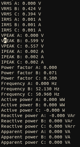
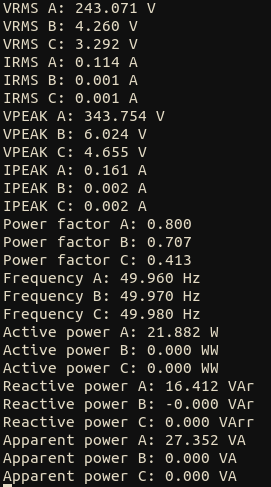
- After the initialization, we start reading from the I2C bus the parameters from all channels (A, B, C) which are the 3 live lines on the PLC. After printing everything, we again move the cursor back on the top to print again.
As it can be seen in the above captures, on the left image there is nothing connected to the live lines, so every relevant value is 0. When the A channel is connected (right image), we can clearly see how the VRMS A is set to 243.071V, and all parameters referring channel A have its correspondent value.