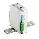
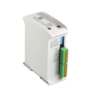
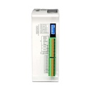
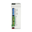
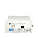
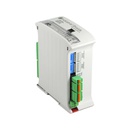
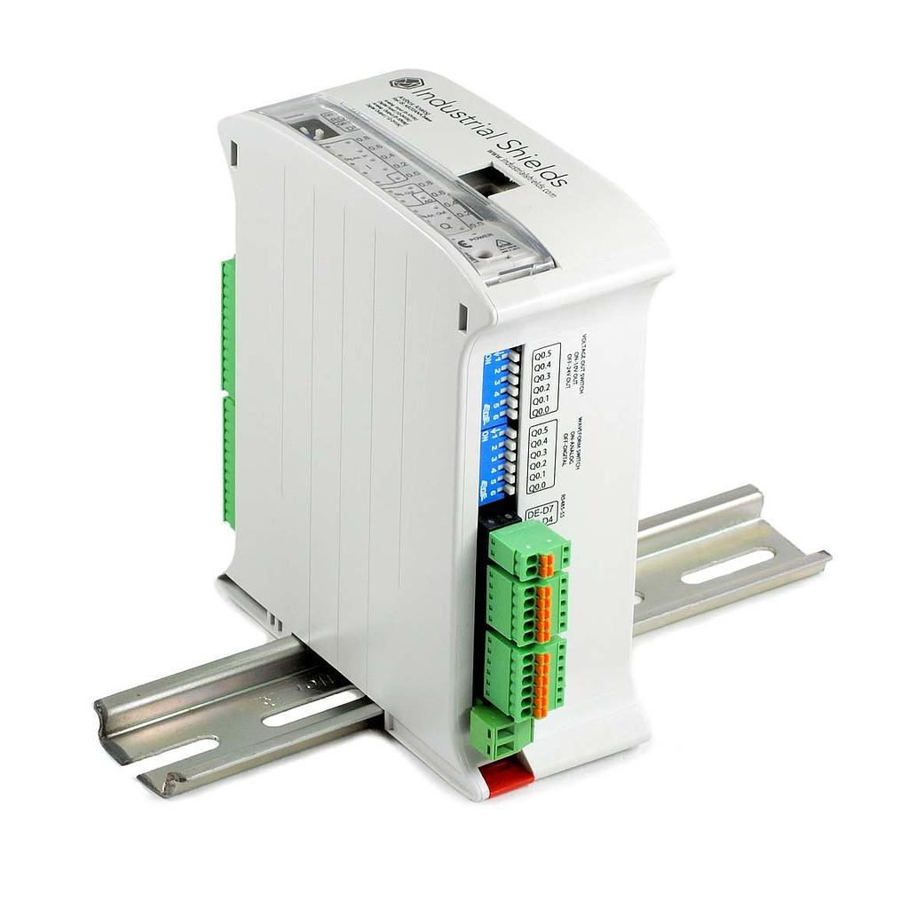
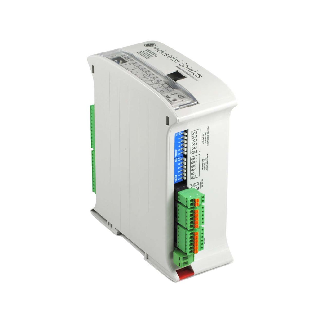
Ardbox Analog: PLC Arduino compacto con 20 E/S y salidas analógicas
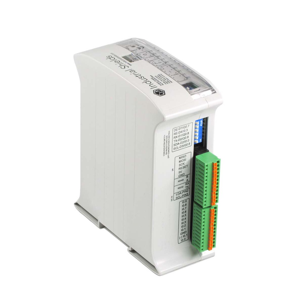
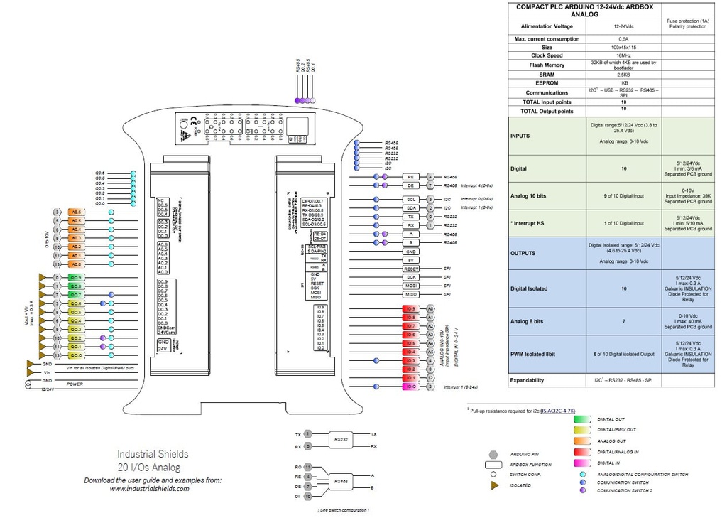
El Ardbox Analog es un PLC industrial compacto de Industrial Shields basado en un Arduino Leonardo original. Tiene 10 entradas (8 analógicas 0-10 V) y 10 salidas (7 analógicas/PWM) en una caja de carril DIN de 45 mm, con RS-485, RS-232, I2C y SPI. Se programa con Arduino IDE, sin licencias, y encaja en pequeña automatización, monitorización de energía y agua y nodos IIoT donde cuentan el espacio y el coste.
¿No tienes claro si es el modelo adecuado? Nuestros ingenieros te ayudan a elegir el controlador y las opciones para tu proyecto.
Hablar con un ingenieroDocumentación
Datasheets
- Datasheet de la familia ArdboxPDF
- Datasheet de la familia Ardbox HF+PDF
- Datasheet de la familia Ardbox HF+ DALIPDF
- Datasheet de la familia Ardbox HF+ LoRaPDF
- Datasheet de la familia Ardbox HF+ GPRSPDF
- Datasheet de la familia Ardbox HF+ Wi-Fi y BLEPDF
Certificados
Guías de usuario
Catálogos
Especificaciones técnicas
| Microcontrolador | Arduino Leonardo (ATmega32u4, 16 MHz, 32 KB flash, 2,5 KB SRAM) |
|---|---|
| Entradas | 10: 8 analógicas/digitales (0-10 V, 10 bits) y 2 digitales optoaisladas, 5 a 24 Vdc, 1 con interrupción |
| Salidas | 10: 7 analógicas/digitales/PWM (0-10 V, 8 bits), 3 digitales optoaisladas, 5 a 24 Vdc |
| Serie y buses | RS-485 (half o full duplex), RS-232, serie TTL, I2C, SPI |
| Programación | Arduino IDE con el paquete de placas de Industrial Shields, micro USB |
| Alimentación | 12 a 24 Vdc, fusible (2,5 A) y protección de polaridad |
| Dimensiones y peso | 100 x 45 x 115 mm, 350 g máx. |
| Entorno | 0 a 60 °C en funcionamiento, 10 a 90 % de humedad sin condensación |
| Montaje y protección | Carril DIN TS35, IP20, dentro de armario |
| Expansión | Expansión I2C hasta 127 elementos. Versiones con Wi-Fi y BLE, GPRS/GSM, LoRa y DALI en los datasheets de familia |
Proyectos con PLC basados en Arduino
Ejemplos probados en campo, con código, hechos con PLC M-Duino y el mismo entorno Arduino IDE.
- Control de enfriadora por Modbus RTUVer el ejemplo
- Control de velocidad de variador por Modbus RTUVer el ejemplo
- Contador de caudalímetro 32 bits por Modbus y reset remotoVer el ejemplo
Antes de elegir el Ardbox Analog
¿Cómo se programa el Ardbox Analog?
Con Arduino IDE (1.8.0 o superior). Instala el paquete de placas de Industrial Shields desde el gestor de placas, selecciona la placa Ardbox y carga por micro USB.
¿Ardbox Analog o Ardbox Relay?
Elige la versión Analog para salidas 0-10 V o PWM con las que mover válvulas, variadores o reguladores. Elige el Ardbox Relay si necesitas conmutar cargas directamente con relés.
¿Tiene Ethernet?
No. El Ardbox comunica por RS-485 y RS-232. Si necesitas Ethernet, mira las familias M-Duino o ESP32 PLC.
¿Puede comunicar por Modbus RTU?
Sí. Usa el puerto RS-485 con las librerías Arduino de Industrial Shields para trabajar como maestro o esclavo Modbus RTU.
Más información del producto
Ardbox Analog: PLC industrial basado en Arduino con 20 E/S
El Ardbox Analog es un PLC industrial compacto en carril DIN basado en Arduino Leonardo. Combina 20 E/S analógicas y digitales con comunicaciones industriales y módulos de conectividad opcionales (LoRa, DALI, GPRS, WiFi & BLE), todo programable con Arduino IDE y sin licencias de software propietario.
Especificaciones técnicas
| Especificación | Detalle |
|---|---|
| Entradas | 8x Analógicas convertibles (0-10 V / 0-20 mA) + 2x Digitales optoacopladas (1 con interrupciones) |
| Salidas | 3x Digitales optoacopladas + 7x Digital/PWM/Analógica |
| Communications | RS485 (HD), RS232, Serial TTL, SPI, I2C |
| Optional modules | LoRa, DALI, GPRS, WiFi & BLE |
| Processor | Arduino Leonardo (ATmega32U4) |
| Mounting | Carril DIN |
| Programming | Arduino IDE |
Variantes disponibles
| Modelo | Tipo de salida | Ideal para |
|---|---|---|
| Ardbox Analog HF+ | 10x Optoacopladas | Control de señales analógicas, monitorización de sensores |
| Ardbox Relay HF+ | 8x Relé | Conmutación directa de cargas, aplicaciones a 230 VCA |
Aplicaciones: Automatización, Energía e Infraestructura inteligente
El Ardbox Analog es ideal para proyectos de automatización pequeños y medianos donde el espacio y el coste son críticos. Su capacidad de medición analógica precisa lo convierte en una solución perfecta para monitorización energética, gestión del agua, automatización de edificios y nodos IIoT.
Protocolos: RS485, Modbus RTU y expansión industrial
RS485 con Modbus RTU incluido de serie para integración fluida con SCADA y HMI. Los módulos opcionales amplían la conectividad a LoRa (IoT de largo alcance), DALI (control de iluminación), GPRS (monitorización remota por SMS) y WiFi & BLE, cubriendo prácticamente cualquier escenario de comunicación industrial.
¿Quieres saber más sobre Modbus y RS485? Lee los siguientes posts 👇
Modbus RTU with Arduino RS485 Troubleshooting
Programación: Arduino IDE, código abierto, sin licencias
Basado en Arduino Leonardo, el Ardbox Analog se programa con el Arduino IDE. El desarrollo es rápido e intuitivo, con un amplio ecosistema de librerías de código abierto y plena propiedad de la lógica de aplicación: sin dependencia del proveedor ni costes recurrentes de software.
Instalación inicial
Arduino IDE
Arduino IDE es la plataforma original para programar placas Arduino. Esta aplicación multiplataforma está disponible en Windows, macOS y Linux bajo la Licencia Pública General de GNU. Arduino IDE es compatible con los lenguajes C y C++. Industrial Shields recomienda usar Arduino IDE para programar los PLCs basados en Arduino, aunque cualquier software compatible con Arduino es compatible con los controladores de Industrial Shields.
Además, Industrial Shields ofrece la posibilidad de seleccionar tu PLC basado en Arduino en el Arduino IDE y compilar tus sketches para los diferentes PLCs.
Descarga el Arduino IDE:
Instala las unidades de Industrial Shields en el Arduino IDE:
Versión Ardbox:
La familia Ardbox consta de 2 modelos principales:
In these models you can add communications (to choose at the time of purchase) such as:
- WIFI & Bluetooth
- GPRS
- DALI
- LoRa
Y puedes elegir entre comunicación RS485 o RS232 en el momento de la compra.
La diferencia entre estos dos PLCs es que, en el modelo Relay, se añaden una serie de relés, mientras que en el modelo Analog se añaden pines analógicos.
Alimentación
Todos los PLCs basados en Arduino pueden alimentarse entre 12-24V. La familia Ardbox tiene un consumo de entre 700 mA y 1500 mA.
Por lo tanto, la fuente de alimentación recomendada es de 2A o superior. Cualquier fuente de alimentación industrial será una buena elección.
REMEMBER:
Out units are designed to be powered between 12-24V. Just powering them with the USB, the unit will not be able to perform their features. USB is just to program the PLC's not to power them.
Si por alguna razón deseas utilizar una fuente de alimentación inferior a 1,5 A, contacta con el soporte técnico de Industrial Shields para asegurarte de que tu sistema funcionará correctamente.
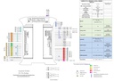
Next is shown a simple diagram to see how to power supply any Industrial Shields unit.
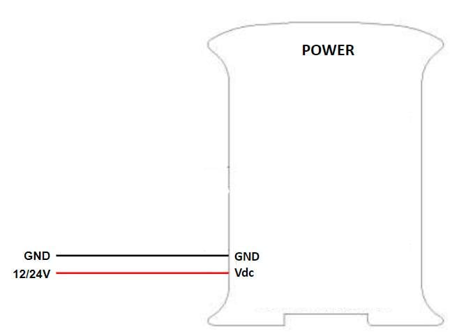
Switch ARDBOX ANALOG
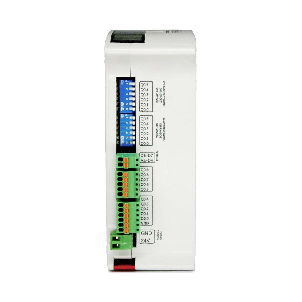
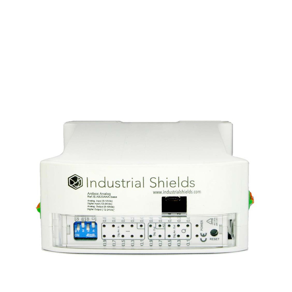
El Ardbox Analog tiene tres áreas de switches diferentes:
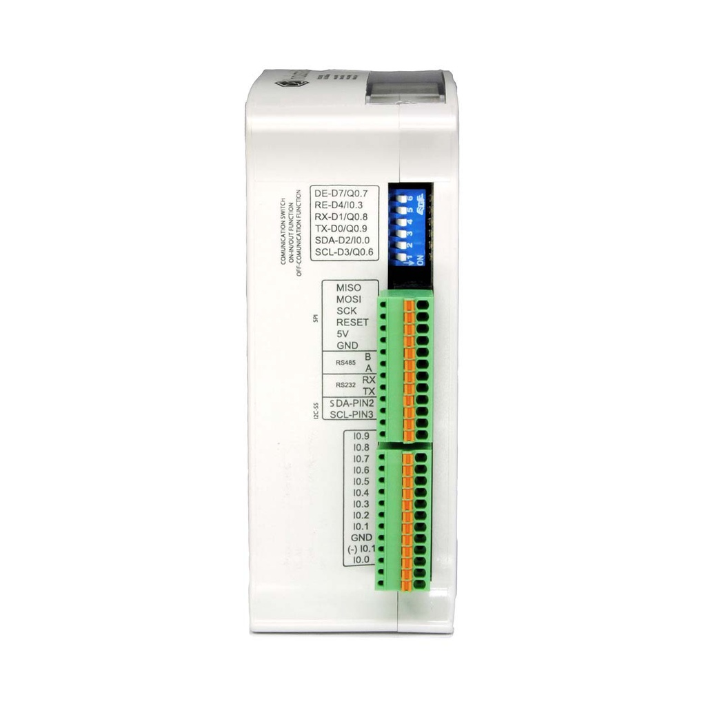
LEFT Zone (Communication SWITCH):
SWITCH | ON | OFF |
1 - SCL/Q0.6 | Q0.6 | SCL |
2 - SDA/I0.0 | I0.0 | SDA |
3 - RS485 RE/I0.9 | I0.9 | RS485 RE |
4 - I0.9/RS485 RE | RS485 RE | I0.9 |
| 5 - RS485 DE/I0.8 | I0.8 | RS485 DE |
6 - I0.8/RS485 DE | RS485 DE | I0.8 |
Zona SUPERIOR (Switch RO-DI):
SWITCH | ON | OFF |
1 - Q0.8 | Q0.8 | RS (RS485) |
2 - RS (RS485) | RS (RS485) | Q0.9 |
3 - Q0.9 | Q0.9 | RS (RS485) |
4 - RS (RS485) | RS (RS485) | Q0.8 |
You cannot use both at the same time, therefore, if the outputs are ON, the RS (RS485) must be OFF and vice versa.
Zona DERECHA (Switch D/A OUT):
SWITCH | ON | OFF |
1 - HD - FD | HALF DUPLEX | FULL DUPLEX |
2 - Q0.6 | DIGITAL (Q0.6) | ANALOG (A0.6) |
3 - Q0.5 | DIGITAL (Q0.5) | ANALOG (A0.5) |
4 - Q0.4 | DIGITAL (Q0.4) | ANALOG (A0.4) |
1 - Q0.3 | DIGITAL (Q0.3) | ANALOG (A0.3) |
2 - Q0.2 | DIGITAL (Q0.2) | ANALOG (A0.2) |
3 - Q0.1 | DIGITAL (Q0.1) | ANALOG (A0.1) |
4 -Q0.0 | DIGITAL (Q0.0) | ANALOG (A0.0) |
The right zone configures the outputs. If the switch is set to "ON" the Q0.X will have the behavior of a digital output. If it is set to “OFF” it will be analog. There is also a switch for switching between Half and Full Duplex. It is “ON” for Half Duplex and “OFF” for Full Dupplex
Switch ARDBOX RELAY
Ardbox Relay has two different switch areas:
Zona SUPERIOR:
SWITCH | ON | OFF |
1 - RS (RS485) | RS (RS485) | R8 |
2 - R8 | R8 | RS (RS485) |
3 - RS (RS485) | RS (RS485) | R7 |
4 - R7 | R7 | RS (RS485) |
Zona DERECHA:
SWITCH | ON | OFF |
1 - NC | - | - |
2 - HD-FD | HALF DUPLEX | FULL DUPLEX |
3 - R5/SCL | R5 | SCL |
4 - I0.0/SDA | I0.0 | SDA |
1 - RE-RS485 | RE-RS485 | I0.4 |
2 - I0.4 | I0.4 | RE-RS485 |
3 - DE-RS485 | DE-RS485 | I0.5 |
4 - I0.5 | I0.5 | DE-RS485 |
Consumo de energía
Ardbox analógico:
Current (mA) | Power (W) | |
Idle | 41,3 | 0,99 |
Full workload | 76,7 | 1,84 |
Ardbox relay:
Current (mA) | Power (W) | |
Idle | 31,83 | 0,76 |
Full workload | 149 | 3,57 |
Entradas y Salidas
Analog inputs
The analog inputs have a tolerance of 0 to 10 Vdc with 10 bits of resolution, they are also isolated and sharing the internal GND. In Digital and Analog I/O there’s self insulation, so its posible to connect them in a different power supply than 24 Vdc.
Ardbox Analog - Inputs: 6 or 8 Analog (0-10Vdc) configurable by Software.
Si se usa la comunicación RS485 (configurada por defecto), solo tendrás 6 entradas analógicas. Para tener 8 entradas analógicas, configúralo en el switch izquierdo: pon I0.8 e I0.9 en ON y RS485 en OFF.
Entradas digitales
Voltage variation from –Vcc (or GND) to +Vcc, with no intermediate values. Two states: 0 (-Vcc or GND) and 1 (+Vcc). In Digital and Analog I/O there’s self insulation, so its posible to connect them in a different power supply than 24 V.
Ardbox Analog - Inputs: 8 or 10 Digital (5-24Vdc).
Si se usa la comunicación RS485 (configurada por defecto), solo tendrás 6 entradas analógicas. Para tener 10 entradas digitales, configúralo en el switch izquierdo: pon I0.8 e I0.9 en ON y RS485 en OFF.
Entradas de interrupción
Interrupt Service Rutine. A mechanism that allows a function to be associated with the occurance of a particular event. When the event occurs the processor exits immediately from the normal flow of the program and runs the associated ISR function ignoring any other task.
Ardbox Analog - Inputs: (1x) Interrupt Inputs (5-24Vdc). “Can work like Digital Input (24Vdc)”.
| Ardbox Pin | Arduino Leornardo Pin | Switch |
| I0.0 (INT1) | 2 | SDA/I0.0 at ON Position |
In this example we activate INT0 using pin I0_0.
Analog outputs
Voltage variation between –Vcc (or GND) and +Vcc, can take any value. An analog input provides a coded measurement in the form of a digital value with an N-bit number. In Digital and Analog I/O there’s self insulation, so its posible to connect them in a different power supply than 24 V.
Ardbox Analog - Outputs: 7 Analog 0-10V output and can convert 7 digital outputs to analog outputs, configurables by Right Switch.
Digital outputs
Voltage variation from –Vcc (or GND) to +Vcc, with no intermediate values. Two states: 0 (-Vcc or GND) and 1 (+Vcc). In Digital and Analog I/O there’s self insulation, so its posible to connect them in a different power supply than 24 V.
Ardbox Analog - Outputs: 10 Digitals (5 to 24Vdc) and 7 of that 10 digital outputs can provide PWM (5 to Vdc).
Relés
Un relé es un interruptor electromagnético controlado por una señal eléctrica. En las unidades de Industrial Shields, estos dispositivos están integrados en las placas y son accesibles directamente con la función digitalWrite(RX, HIGH). Los relés de Industrial Shields son normalmente abiertos y pueden manejar una corriente máxima de 4A para 230Vca y 2A para 24Vcc.
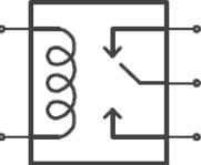
Ardbox Relay - Outputs: 8 Relay outputs (220Vac – 5A). (R1, .. , R8)
Salida PWM
Modulación por Ancho de Pulso (PWM). Activa una salida digital durante un tiempo y la mantiene apagada el resto. La tensión de salida media, en el tiempo, será igual al valor analógico deseado. La frecuencia entre pulsos es la misma mientras cambia el ancho del pulso.
A PWM Output gives a Vcc value during a certain time.
Pay attention to the supply voltage, because the PWM output will have the same voltage difference.
| Ardbox Pin | Arduino Pin |
| Q0.6 | 3 |
| Q0.5 | 5 |
| Q0.4 | 6 |
| Q0.3 | 9 |
| Q0.2 | 10 |
| Q0.1 | 11 |
| Q0.0 | 13 |
- Q0.0, Q0.1, Q0.2, Q0.3, Q0.4, Q0.5 and Q0.6 Digital/PWM out also as A0.0, A0.1, A0.2, A0.3, A0.4, A0.5 and A0.6 Analog out.
Module Pulses from avr-Pulses library
The Pulses module provides functions for starting and stopping a train of pulses at the desired frequency using PWM pins. The
startPulses(pin, frequency, precision) function starts the train of pulses at the specified frequency and precision. The default frequency is 1kHz and the default precision is 3.
The stopPulses(Pin) function stops the train of pulses.
IMPORTANT:
It is not possible to have different frequencies between the same TIMER Pin’s. Some outputs share the same timer, so they work at the same frequency.
CAUTION!!!
When the TIMER0 pins are used, all the time functions change their functionality as delay() , millis() , micros() , delayMicroseconds() and others.
Next it is showed recommended precision between different frequencies:
| Precision | Frequency Range (Hz) |
| 1 | 30 - 150 |
| 2 | 150 - 500 |
| 3 | 500 - 4k |
| 4 | 4k - 32k |
| 5 | 32k - 4 |
To have a high precision on the desired frequency, it is recommended to use the closer precision to the values of the previous table.
Example Code
In Ardbox RELAY there's no PWM Output.
Protocolos de comunicación
RS-485
RS-485, also known as TIA-485(-A), EIA-485, is a standard defining the electrical characteristics of drivers and receivers for use in serial communications systems. The electrical signaling is balanced, and multi-point systems are supported.
Make sure you have your switches and jumpers configured properly before using this serial communication.
Ejemplo de uso
Ejemplo básico de escritura RS-485 (envío):
Basic RS-485 read example (receive):
Ejemplo básico RS-485 full-duplex:
* Recuerda que para probar el full duplex con tu PLC Ethernet debes conectar A, B (receptores) a Y, X (transmisores).
RS-232
RS-232, también conocido como TIA-232-F, EIA-232-F o V.24, es un estándar para la transmisión de datos en comunicación serie. Especifica los niveles de tensión, la temporización de señales y el protocolo de comunicación entre dispositivos.
Make sure you have your switches and jumpers configured properly before using this serial communication.
Ejemplo de uso
Ejemplo básico de escritura RS-232
Basic RS-232 read example
I2C
I2C is a synchronous protocol that only uses 3 cables, one for the clock (SCL) and one for the data (SDA) and ground (GND). This means that the master and the slave send data through the same cable, which is controlled by the master, who creates the clock signal. I2C uses addressing to select slaves.
I2C is a serial communications bus. The speed is 100 kbit/s in standard mode, but also allows speeds of 3.4 Mbit/s. It is a very used bus in the industry, mainly to communicate microcontrollers and their peripherals in integrated systems, or to communicate integrated circuits that reside in a same PCB.
Make sure you have your switches and jumpers configured properly before using this serial communication.
Ejemplo de uso
IMPORTANT: Make sure to download the Arduino based PLC boards for Arduino IDE.
Ejemplo básico de escaneo I2C:
SPI
SPI is a synchronous communication protocol bus that has a master-slave architecture. Slave devices cannot initiate communication, nor exchange data with each other directly. Only the master can select to which slave will communicate with through the SS (slave select) pin.
Ejemplo de uso
Funciones adicionales
Pines directos de Arduino
If we want to use another Serial Port using your equipment, we can make use of some digital pins to create a Serial. The SoftwareSerial library has been developed to allow serial communication on other digital pins of the Arduino, using software to replicate the functionality. It is possible to have multiple software serial ports with speeds up to 115200 bps. A parameter enables inverted signaling for devices which require that protocol.
Only I/O 5V from Ardbox or M-Duino boards can be used.
| M-Duino Pins | Leonardo Pins |
| MISO | 14 |
| MOSI | 16 |
| SCK | 15 |
5VDC Signals
These pins can be programmed according to Arduino features such as I/Os operating at 5V or any additional features present in the pins.
I2C Pins – SDA/SCL:
El protocolo I2C está diseñado para funcionar en configuración pull-up. En este caso, lee 5V cuando no hay nada conectado.
SPI – MISO/MOSI/SCK:
Estos pines solo pueden funcionar como pines de 5V si no se va a usar el protocolo Ethernet. Como Ethernet usa SPI para comunicarse con la placa Arduino, ambos comportamientos no pueden coexistir simultáneamente.
Pin2/Pin3:
These pins are only referred to the inputs I0.5/I0.6. If the switch configuration is in OFF position the pins Pin 2/Pin 3 will be available.