Introduction
PROFINET is an open Industrial Ethernet solution based on international standards. It is a communication protocol designed to exchange data between controllers and devices in an automation setting for industrial control.
In this post, we will run the p-net PROFINET device stack and its sample application on industrial Raspberry PLC as an IO-device, and we will configure a second Raspberry Pi industrial PLC as an IO-controller with Codesys.
Related Links
PROFINET
PROFINET is an industry technical standard for data communication over industrial Ethernet, designed for collecting data from, and controlling equipment in industrial systems, with particular strength in delivering data under tight time constraints. PROFINET supports you in creating integrated processes with real-time communication and connecting them up to the cloud via OPC UA.
The openness and flexibility of PROFINET mean you enjoy maximum freedom when designing your machine and system structure. Its efficiency allows you to use available resources optimally, while significantly increasing plant availability. PROFINET's performance sustainably increases productivity.
To ensure appropriate performance, PROFINET delivers data through the following communication channels:
- TCP/IP (or UDP/IP)
- PROFINET Real-Time (RT)
- PROFINET Isochronous Real-Time (IRT)
- Time Sensitive Networking (TSN)
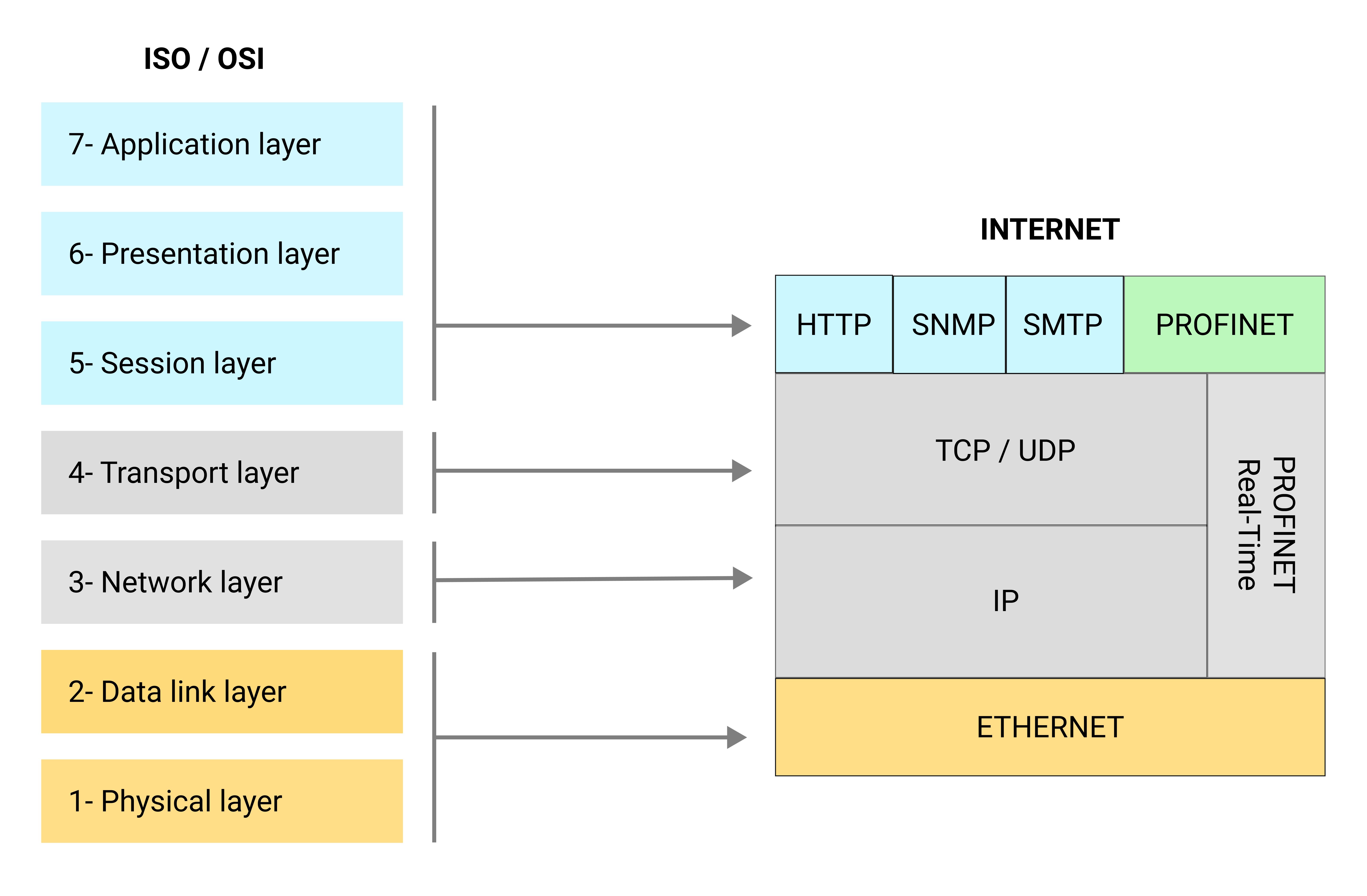
Look at the ISO/OSI model, a seven-layer model that generically describes the abstraction layers of a communication system. Any network communication can be divided into a number of layers.

Ethernet sits on Layer 1 (physical layer) and Layer 2 (data link layer) of the ISO/OSI model. Ethernet frames include information such as the MAC addresses of sender and receiver, virtual LAN (VLAN) tagging, and Quality of Service (QoS).
PROFINET sits on Layer 7 of the ISO/OSI model since it is an application. It defines cyclic and acyclic communication between components, including diagnostics, functional safety, alarms, and other related information. Also, PROFINET is based on standard Ethernet for its communication medium.
High bandwidth, large message size, and versatility are just some of the benefits of having Ethernet in the industrial environment.
Tutorial
In this post, we will run the p-net PROFINET device stack and its sample application from rt-labs for industrial automation. We are going to implement a PROFINET IO-device, having an IO-module with 8 digital inputs and 8 digital outputs, and a Raspberry Pi based PLC as IO-Controller running the Codesys runtime for Raspberry Pi automation. Once we manage to get the sample application running on our Raspberry PLCs, we will be able to communicate both Raspberry PLC with PROFINET.
Requirements
- 2x Raspberry PLC
- USB Ethernet hub
- 1x Power Supply
- 2x Ethernet cables
- Windows laptop (or Windows Virtual Machine) with CODESYS
- Linux laptop or a screen with HDMI cable to connect to your Raspberry Programmable Logic Controller through SSH
IO-Controller Setup
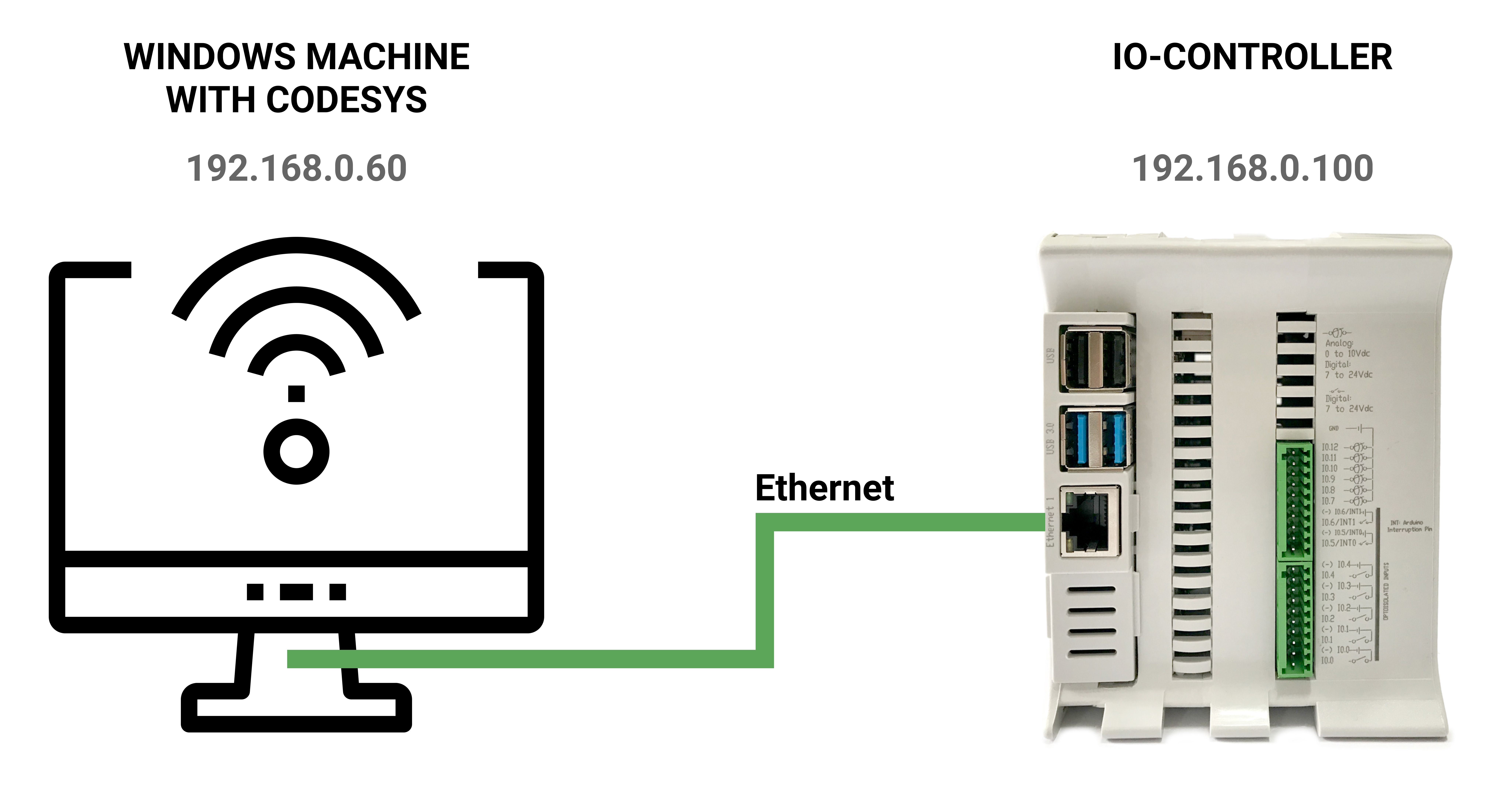
1. First of all, set a static IP address for Ethernet from your Windows laptop: 192.168.0.60. Connect an Ethernet cable from your Windows laptop to your industrial Raspberry Pi PLC and connect through SSH:
Alternatively, you can connect a micro HDMI cable from the Raspberry PLC to a monitor.
Set a static IP address for the interface eth0 from your Raspberry PLC IO-Controller: 192.168.0.100.

2. Go to your Windows laptop, and download and install the CODESYS Development System V3 and the CODESYS Control for Raspberry Pi SL. A free trial version is available. Registration is required. And with the trial version, you'll need to restart the Codesys runtime on the Raspberry PLC every two hours.
3. Once installed, open Codesys and create a new standard project. In the next window that shows up, select device "Codesys Control for Raspberry Pi SL" and select to program in "Structured Text (ST)".
Note: If you cannot see the device "Codesys Control for Raspberry Pi SL" that means that the installation was not successful. Try again and verify that your device in the left menu shows as "Codesys Control for Raspberry Pi SL".
4. In the top menu, use Tools > Update Raspberry Pi > Type Username and Password > Scan your "IP address". Select the static IP of the Raspberry Pi (For ex. for this tutorial, 192.168.0.100).
5. Double-click the "Device (CODESYS Control for Raspberry Pi SL)" > Click the "Scan Network" tab and select your Raspberry PLC. The marker on the image should turn green. To verify the communication, go to the Device tab and "Send Echo Service".
Note: If you get any issue, right-click on the Device (CODESYS Control for Raspberry Pi SL) > Update Device... > Display all versions (for experts only) > And select the same version that you chose when you created the new project, in this case: CODESYS Control for Raspberry Pi SL - Version 4.0.1.0. And try again step 5.
6. Go to the rt-labs Github and save this file on your Windows laptop.
7. Go back to Codesys, in the top menu "Tools", select "Device Repository" > Install > select the GSDML file that you just saved.
8. On the "Device (CODESYS Control for Raspberry Pi SL)" in the device panel, right-click and select "Add Device..." > Ethernet adapter > Ethernet.
9. Right-click on this Ethernet > select "Add Device..." > "Profinet IO" > "Profinet IO Master" > "PN_Controller".
10. Right-click on this "PN_Controller (PN-Controller)" > Select "Add device... " > "P-Net Sample App".
11. Right-click on the "P_Net_Sample_App (P-Net Sample App)" > Select "Add Device..." > "Fieldbuses" > "Profinet IO" > "Profinet IO Module" > "DIO 8xLogicLevel".
12. Go to the Ethernet from step 8 and double click > Select interface "eth0". The IP address will be updated accordingly.
13. Go to the "PN_Controller" in the left menu and modify the First IP address 192.168.0.50 and the Last IP Address 192.168.0.60 .
14. Go to the "P_Net_Sample_App" node in the left menu > IP Parameter > Set the IP-address to the existing address to the existing address of your IO-Device: 192.168.0.50.
15. Go to your project in the left panel > Device (CODESYS Control for Raspberry Pi SL) > PLC Logic > Application > PLC_PRG (PRG).
16. There are two sections, the variables section on the top and the program section on the bottom.
Variables section
PROGRAM PLC_PRG VAR in_pin_button_LED: BOOL; out_pin_LED: BOOL; in_pin_button_LED_previous: BOOL; flashing: BOOL; oscillator_state: BOOL := FALSE; oscillator_cycles: UINT := 0; END_VAR
Program section
oscillator_cycles := oscillator_cycles + 1;
IF oscillator_cycles > 200 THEN
oscillator_cycles := 0;
oscillator_state := NOT oscillator_state;
END_IF
IF in_pin_button_LED = TRUE THEN IF in_pin_button_LED_previous = FALSE THEN flashing := NOT flashing; END_IF out_pin_LED := TRUE; ELSIF flashing = TRUE THEN out_pin_LED := oscillator_state; ELSE out_pin_LED := FALSE; END_IF in_pin_button_LED_previous := in_pin_button_LED;
17. Right-click the "DIO_8xLogicLevel" > "Edit IO mapping..." > Double-click the icon of the "Input Bit 7" > Click the [...] button > Go to Application > PLC_PRG > "in_pin_button_LED".
18. Right-click the "DIO_8xLogicLevel" > "Edit IO mapping..." > Double-click the icon of the "Output Bit 7" > Click the [...] button > Go to Application > PLC_PRG > "out_pin_LED".
19. Double-click on the Application > "Task Configuration" > MainTask > Select "Cyclic" > 4 ms.
20. Double-click on the Application > "Profinet_CommunicationTask" > Select "Cyclic" > 10 ms. Use priority 30.
21. In the top menu, go to Build > Generate Code.
22. In the top menu, go to Online > Login, to transfer the application to the Raspberry Pi. Select "Yes" in the pop-up window.
23. Go to the top menu Tools > "Update Raspberry Pi" > System info, and look in the "Runtime Info" text box to follow the controller logs.
24. Once the IO-Controller has been configured, you can turn off the Windows machine running the Codesys application.
Remember that you need to power cycle the Raspberry PLC IO-Controller every two hours if using the trial version.
25. Install Wireshark. Check that your Raspberry PLC IO-Controller sends LLDP packets every 5 seconds.
IO-Device Setup
25. Now, let's configure the IO-Device to run the PROFINET application from rt-labs.
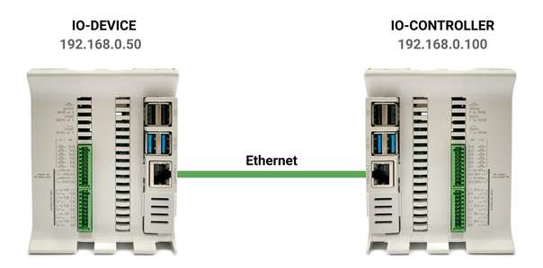
26. Power up the IO-Device Raspberry PLC, change its IP address to 192.168.0.50 and plug it in into the Raspberry PLC IO-Controller.

27. Connect your open source PLC Raspberry pI to the Internet via LAN or WiFi to be able to download software.
28. In order to compile p-net on Raspberry, you need to download some packages first:
sudo apt update
sudo apt install snapd
sudo reboot
sudo snap install cmake --classic
29. Verify the installed version:
cmake --version
30. Install git:
sudo apt install git
31. Create a directory called profinet:
mkdir /home/pi/profinet
cd /home/pi/profinet
32. Clone the source:
git clone --recurse-submodules https://github.com/rtlabs-com/p-net.git
33. Configure and create the build:
cmake -B build -S p-net
34. Build the code:
cmake --build build --target install
35. Configure and create the build:
cmake -B build -S p-net
36. Run this command from the profinet directory:
snap run cmake -B build -S p-net -DCMAKE_BUILD_TYPE=Debug -DBUILD_TESTING=OFF -DBUILD_SHARED_LIBS=ON -DUSE_SCHED_FIFO=ON
37. Go to the build directory:
cd build
38. We are going to test this application with plain files. So, make two files to simulate buttons:
touch /home/pi/profinet/build/button1.txt
touch /home/pi/profinet/build/button2.txt
39. Run the application with the two plain files buttons:
sudo ./pn_dev -vvvv -b /home/pi/profinet/build/button1.txt -d /home/pi/profinet/build/button2.txt
40. If you only have one terminal, you need to run the application in the background to manually write 1 or 0 to the /home/pi/profinet/build/buttonX.txt to change its values like this:
echo 1 > /home/pi/profinet/build/button1.txt
echo 0 > /home/pi/profinet/build/button1.txt
For more information about the tutorial, please visit this link .
Now it is your turn!
Now it is time for you to start developing your own applications. You can use the sample app as a starting template. Experiment by modifying the available modules, and the data types they send and receive. Modify your GSDML file accordingly to explain the IO-device behavior to the PLC configuration tool!
PROFINET & Raspberry PLC tutorial: How to trigger alarms using CODESYS