

This article is the second in a series on using the Industrial Shields ESP32 PLC with Arduino Cloud. It shows how to add a cloud variable, configure the network, upload the sketch, and build a dashboard to control a digital output remotely. Make sure you have completed the first part before continuing.
Getting started with the ESP32 PLC and Arduino Cloud
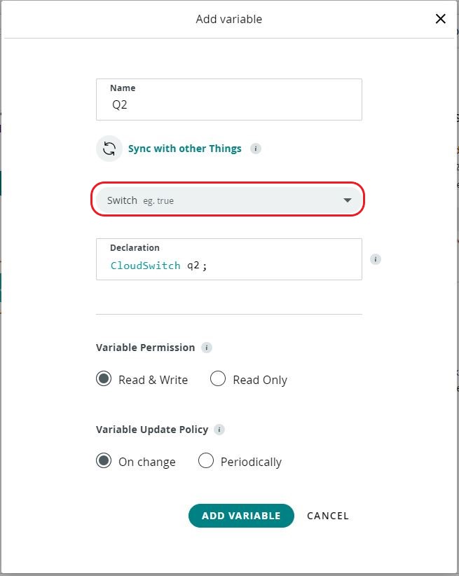
Step 1: add a cloud variable
Inside your thing, click Add Variable and select the CloudSwitch type from the dropdown. Name it according to the output you want to control. In this example the variable is called q2 and will control output Q0_2.

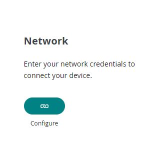
Step 2: configure the network
Once the variable is created, go to the Network section of your thing. Enter the SSID and password of the WiFi network the ESP32 PLC will connect to, and the Secret Key you saved when registering the device.
Step 3: get the sketch and upload it
Go to the Sketch tab of your thing and click Open Full Editor. The web editor shows four files. You need two of them: main.ino (or whatever your sketch is named) and thingProperties.h. Copy the content of both files into a new Arduino project on your computer. You will also need the values from the Secret file.

Select your ESP32 PLC model under Tools > Board, add Q0_2 as an output, and upload the sketch. The files will look like this:
main.ino
#include "thingProperties.h"

void setup() {
  pinMode(Q0_2, OUTPUT);
  Serial.begin(9600);
  delay(1500);
  initProperties();
  ArduinoCloud.begin(ArduinoIoTPreferredConnection);
  setDebugMessageLevel(2);
  ArduinoCloud.printDebugInfo();
}

void loop() {
  ArduinoCloud.update();
  onQ2Change();
}

void onQ2Change() {
  if (q2 == true) {
    digitalWrite(Q0_2, HIGH);
  } else {
    digitalWrite(Q0_2, LOW);
  }
}
thingProperties.h
// Code generated by Arduino IoT Cloud, DO NOT EDIT.
#include <ArduinoIoTCloud.h>
#include <Arduino_ConnectionHandler.h>

const char THING_ID[]          = "YOUR_THING_ID";
const char DEVICE_LOGIN_NAME[] = "YOUR_DEVICE_ID";
const char SSID[]              = SECRET_SSID;
const char PASS[]              = SECRET_PASS;
const char DEVICE_KEY[]        = SECRET_DEVICE_KEY;

void onQ2Change();
CloudSwitch q2;

void initProperties() {
  ArduinoCloud.setBoardId(DEVICE_LOGIN_NAME);
  ArduinoCloud.setSecretDeviceKey(DEVICE_KEY);
  ArduinoCloud.setThingId(THING_ID);
  ArduinoCloud.addProperty(q2, READWRITE, ON_CHANGE, onQ2Change);
}

WiFiConnectionHandler ArduinoIoTPreferredConnection(SSID, PASS);
Replace YOUR_THING_ID and YOUR_DEVICE_ID with the actual values from your device page in Arduino Cloud. The SECRET_SSID, SECRET_PASS and SECRET_DEVICE_KEY values come from the Secret tab in the web editor.
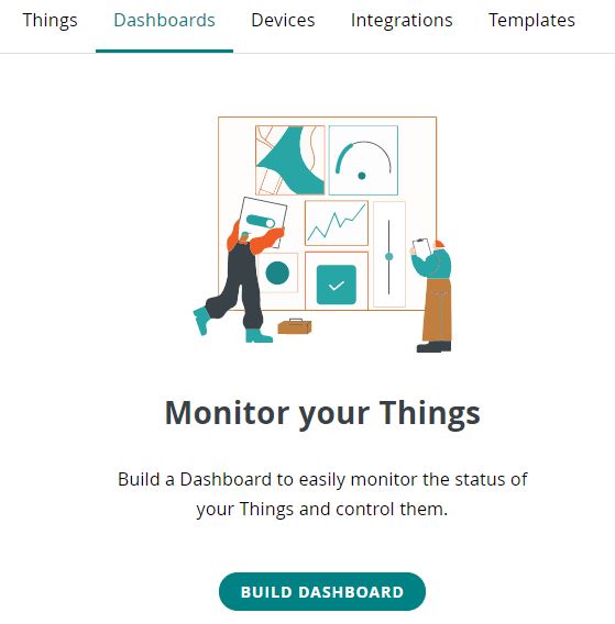
Step 4: build the dashboard
Go to the Dashboards tab in Arduino Cloud and click Build Dashboard (or Create Dashboard).
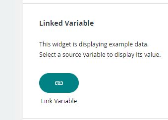
Click Add and select the Switch widget.
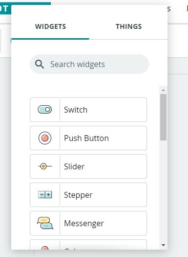
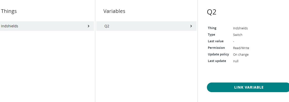
In the widget settings, click Link Variable and select the q2 variable you created in step 1.
Testing the system
Upload the sketch to the ESP32 PLC and open the serial monitor. Once the PLC connects to the WiFi network and syncs with Arduino Cloud, you can toggle the switch in the dashboard to turn Q0_2 on and off. The connection status is visible in the serial monitor output.
The next article in the series will show how to read a sensor value from the ESP32 PLC and display it as a chart in the Arduino Cloud dashboard.
Controlling ESP32 PLC digital outputs with Arduino Cloud