Case study · Greenhouse · M-Duino 57R
A radio node in each room. One PLC acts where it is needed.
Low-power Open Mote nodes, a Panel PC and an Arduino based PLC.
A greenhouse with several rooms has several climates. A value that is wrong in one room says nothing about the next one.
So the case puts a radio node in each room and one PLC in the main room.
This case describes how a customer monitors and controls a greenhouse with Open Mote radio nodes, an Industrial Shields Panel PC and an M-Duino 57R I/Os PLUS. It does not name the customer. The hardware, the readings, the radio and the layout come from the case, its text and its scheme. The values in the panels are examples, not data from the greenhouse.
The challenge
Know the climate of every room, and act only where a value is wrong.
The greenhouse has a main room and other rooms. The customer wanted to read several sensors in each room, to see all the data in one place and to start the actuators of the room where a value is not wanted. The sensors had to talk to the terminal without wires, so the nodes can go wherever they suit the room.
One climate per room
Each room has its own Open Mote with a sensor board for humidity, temperature, pressure and brightness. The data of one room is kept apart from the others.
Nodes where they fit
The radio link lets you place the nodes throughout the greenhouse. All of them send to a single Open Mote that works as the gateway.
Low power
The case gives a consumption of less than 50 µA for the Open Mote, which is why it can work for a long time on its own.
One screen for all
The gateway node plugs into the USB port of the Panel PC. The data of every room ends up on one screen.
Radio for the readings, wires for the loads
The nodes only carry small readings by radio. The fans, valves and pumps are wired to the relay outputs of the PLC in the main room. The case does not publish results or figures.
How it works
Three jobs: read every room, check the values, act in the right room.
Each panel shows one job. Press the buttons. The panels are illustrative simulations: the rooms, the four readings, the radio and the three relays per room come from the case, but the values, the ranges and which relay answers which value are examples, not data from the greenhouse.
Four values per room, sent by radio.
In each room an Open Mote with its sensor board reads humidity, temperature, pressure and brightness. It sends the values on 2.4 GHz, with the free Contiki software, to the gateway node in the main room. Pick a room and watch its messages.
- One Open Mote and one sensor board per room
- Radio on 2.4 GHz, Contiki
- One Open Mote as the gateway
Radio messages (example)
Illustrative simulation. Example values, not data from the greenhouse. One message every few seconds, faster than in the real greenhouse. The case does not publish the reading interval or the values. The units are examples.
The Panel PC sees every room and spots the wrong value.
The gateway node sits on the USB port of the Panel PC. In the scheme of the case the Panel PC runs Node-RED and a Mosquitto MQTT broker. It shows the data and, when a value from a room is not wanted, it notifies the PLC over the Ethernet cable. Move the sliders.
- Gateway node on USB
- Node-RED and Mosquitto MQTT on the Panel PC
- Ethernet from the Panel PC to the PLC
Panel PC events (example)
Illustrative simulation. Example values, not data from the greenhouse. The case says that the PLC is notified when a value sent by a node is unwanted. It does not publish the ranges. In this example: humidity from 60 to 85 %RH and temperature from 15 to 28 °C. Set yours for your crop.
Only the room with the problem gets its actuators on.
The M-Duino 57R I/Os PLUS in the main room has the actuators wired to its relay outputs. When it gets a notice, it switches the actuators of the room where the unwanted value was detected. The other rooms stay as they are. Press the buttons.
- Actuators on the relay outputs
- 3 relays per room in the scheme: fan, valve, pump
- The other rooms do not change
M-Duino events (example)
Illustrative simulation. Example values, not data from the greenhouse. The scheme of the case gives 3 relay outputs to each of the 4 rooms, with a fan, a valve and a pump. Which relay answers which value is an example: the case does not publish its rules.
Try it on a full greenhouse
Run the same pattern on a simulator.
The panels above show the logic one step at a time. The simulators below run a whole site, day and night.
Radio nodes, one gateway, a day and a night
Choose the site "Greenhouse". Watch the humidity and the dew point at night, then block a link, drain a battery or cut the gateway. It uses a GateBerry FLEX gateway; the logic is the same.
Open the simulatorSimulator · Greenhouse climateClimate control by zone
Set the targets of each zone and see how a PLC acts on ventilation, heating and humidity. It is the control side of this case.
Open the simulatorSystem architecture
How do you control several greenhouse rooms with wireless sensors?
Put one radio node with its sensors in each room, and one receiver, the PLC and the screen in the main room. In this case each room has an Open Mote with a sensor board for humidity, temperature, pressure and brightness. The nodes send their values on 2.4 GHz to an Open Mote that works as the gateway, plugged into the USB port of an Industrial Shields Panel PC. The Panel PC shows the data and, when a value is not wanted, notifies an M-Duino 57R I/Os PLUS over Ethernet. The PLC switches the actuators of that room on its relay outputs.
| Signal | Between | Type | Purpose |
|---|---|---|---|
| Room climate | BetweenSensor board → Open Mote | TypeHumidity, temperature, pressure, brightness | PurposeOne sensor board on the Open Mote of each room |
| Room readings | BetweenOpen Mote of each room → gateway | TypeRadio, 2.4 GHz, Contiki | PurposeSends the values of the room to the main room |
| Collected data | BetweenGateway Open Mote → Panel PC | TypeUSB | PurposeAll the rooms reach the Panel PC |
| Monitoring | BetweenPanel PC → user | TypeNode-RED, Mosquitto MQTT | PurposeShows the data of every room; software from the scheme of the case |
| Notice | BetweenPanel PC → M-Duino | TypeEthernet | PurposeSent when a value from a room is not wanted |
| Actuators | BetweenM-Duino → each room | Type3 relay outputs per room | PurposeFan, valve and pump in the scheme of the case |
Why it works
Small readings by radio, power where it is needed.
No sensor cables across the rooms
The radio link means the nodes can go wherever they suit each room. Moving a node does not mean pulling a new cable.
Low power in the nodes
With less than 50 µA of consumption, as the case gives it, the Open Mote can work for a long time on its own.
One gateway, one screen
All the rooms meet in one gateway node and one Panel PC. One place to see the whole greenhouse.
Open software on the Panel PC
Node-RED and a Mosquitto MQTT broker run on the Panel PC in the scheme. See a Node-RED MQTT concentrator and a central Mosquitto MQTT broker.
Relays for real loads
The actuators are wired to the relay outputs of the M-Duino, which can switch loads directly. The M-Duino 57R has 23 relays, and the scheme uses 12.
Programmed with free tools
The PLC is programmed with the Arduino IDE. The rules of each room are code that you can read and change.
From the original case
The scheme and the sensor board of the case.
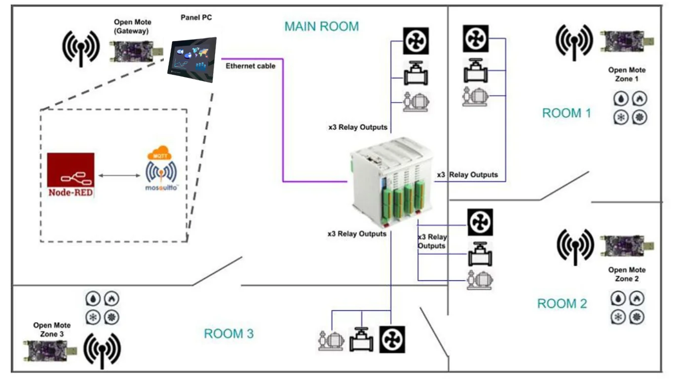

The case does not publish photos of the installation.
Hardware
The PLC and the Panel PC of today. The nodes of the case.

M-DUINO ETHERNET PLC ARDUINO 57R
The case names the M-Duino 57R I/Os PLUS. Today this PLC is sold as the M-DUINO ETHERNET PLC ARDUINO 57R. It sits in the main room and drives the actuators of every room.
- Role in this design
- Gets the notices of the Panel PC and switches the actuators of each room
- Inputs
- 18: 12 analog or digital (0-10 V), 6 digital optoisolated
- Outputs
- 31: 23 relays (230 Vac 4 A, resistive), 8 analog, digital or PWM (0-10 V)
- Comms
- Ethernet (RJ45), RS-485, RS-232, TTL, I2C, SPI
- Power supply
- 12 to 24 Vdc
- Mounting
- DIN rail TS35, IP20
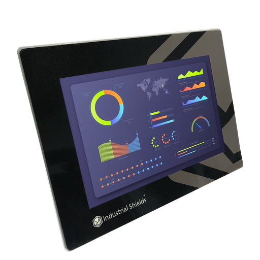
Panel PC with Raspberry Pi
An Industrial Shields Panel PC takes the gateway node on USB, shows the data of every room and notifies the PLC over Ethernet.
- Role in this design
- Gateway on USB, monitoring, notice to the PLC
- Software in the scheme
- Node-RED, Mosquitto MQTT broker
- Links
- USB to the gateway node, Ethernet to the PLC
The case does not publish the exact Panel PC model. The image shows the TouchBerry Pi Panel PC 10.1" FLEX.

OpenMote B (image from the original case)
One Open Mote with a sensor board in each room, and one more on the USB port of the Panel PC as the gateway.
- Sensors
- Sensor board with humidity, temperature, pressure and brightness
- Inputs
- Digital and analog, for other sensors
- Radio
- 2.4 GHz antenna, free Contiki software
- Consumption
- Less than 50 µA, as the case gives it
OpenMote is no longer in the Industrial Shields catalogue. The pattern still applies: low-power radio nodes, one receiver, a Panel PC and a PLC with relays. Tell us your rooms and we will propose the nodes and the radio.
Questions about this case
How do you monitor several greenhouse rooms without sensor cables?
With one radio node in each room. In this case each room has an Open Mote with a sensor board that sends its values on 2.4 GHz to a gateway node in the main room. The gateway is plugged into a Panel PC by USB, so the data of every room is on one screen.
What does each node measure in this case?
Humidity, temperature, pressure and brightness, with the Open Mote sensor board. The Open Mote also has digital and analog inputs for other sensors.
How does a value from a room reach the PLC?
The node sends it by radio to the gateway node. The gateway passes it to the Panel PC over USB. If the value is not wanted, the Panel PC notifies the M-Duino over Ethernet, and the PLC switches the actuators of that room.
Which actuators does the PLC switch?
The actuators are wired to the relay outputs of the M-Duino. The scheme of the case gives 3 relay outputs to each of the 4 rooms, with a fan, a valve and a pump. The case does not publish the rules that link each value to each relay.
Can I build this today?
Yes. The PLC of the case is sold today as the M-DUINO ETHERNET PLC ARDUINO 57R, and the Panel PCs with Raspberry Pi are in the catalogue. OpenMote is no longer in the catalogue, so tell us your rooms and your variables and we will propose the radio nodes and the gateway.
How is this case different from the other greenhouse case?
In the other greenhouse case two M-Duino PLCs read wired sensors on an I2C bus and control humidity, CO2, temperature and lights. Here the sensors are wireless: one radio node per room, a gateway on a Panel PC and one PLC with relays for all the rooms.
Download the case study
4-page PDF with the challenge, the logic, the architecture and the hardware. No form required.
Rooms with different climates?
Tell us your rooms and your variables. An engineer will answer.
Tell us how many rooms or zones you have, what you want to measure in each one, which actuators you need to switch and where the data must go. We will propose the sensors, the radio, the PLC and the screen.
- You get an answer from our technical team
- Sensors, radio, PLC and Panel PC for your greenhouse
- Arduino, ESP32 or Raspberry Pi based PLCs