Case study · Fluid transport and storage · ESP32 PLC
Fluids on the move. A PLC that watches them.
Pressure, temperature, level, quality and composition, from the sensor to the dashboard.
A fluid has to arrive as it left. Not only on time.
So the system watches it during the trip and in storage, and speaks up when a value moves.
This case study describes a monitoring system for liquids and gases during transport and storage. The client, the fluid and the exact ESP32 PLC model are not published. The parameters, the sensors, the dashboard and the two kinds of notification come from the case. The values and limits in the panels are examples.
The challenge
Keep a fluid safe and fit for use while it travels.
Liquids and gases can be contaminated or deteriorate during transport and storage. Automatic systems keep the conditions in range and detect deviations early, so the team can take preventive or corrective measures.
Five things to watch
Pressure, for safe and optimal conditions. Temperature, away from extremes that change the fluid. Level, for the right volume with no overflow or shortage. Quality, against the required specifications. Chemical composition, against contamination.
Sensors that depend on the fluid
The case uses Mettler Toledo amperometric sensors, Pt100 temperature sensors and other specific sensors, such as compression or viscosity, chosen for each fluid.
Mixed connections
Some sensors connect through common interfaces, others through the analog or digital inputs of the PLC. One controller has to read them all.
Information where it is needed
The readings go to a monitoring system on the transport and appear on a dashboard with several data screens.
The goal
Guarantee the safety and the quality of the fluid by detecting incidents in time. Keep the fluid fit for the process where it will be used. And optimise transport and storage, to reduce costs and improve the performance of the process.
How it works
Three jobs: read the sensors, judge the change, keep sending.
Each panel shows one job. Press the buttons. The panels are illustrative simulations: the parameters, the dashboard and the two kinds of notification come from the case. The ranges, the limits, the intervals and the messages are examples.
From a current to a value.
The case connects some sensors to the analog inputs of the PLC. The inputs of the ESP32 PLC measure 0 to 10 V. Many industrial transmitters give 4 to 20 mA, so a shunt turns the current into a voltage and the program scales it. Change the current, then cut the wire.
- 4 mA is the bottom of the range, 20 mA the top
- A 500 Ω shunt gives 2 to 10 V
- No current is a fault, not a zero
Illustrative simulation. Example values, not data from the case. Example: a 4-20 mA pressure transmitter with a 0 to 10 bar range and a 500 Ω shunt on a 0-10 V input. Below 3.6 mA the reading is treated as a fault (NAMUR NE 43). The case does not publish the ranges or the wiring of each sensor.
A recurring status. An alert when it matters.
The case programs two kinds of notification: a recurring status of the fluid, and an alert when a key indicator has an unexpected or alarming variation. A typical way to do it: one limit for the value and one for its rate of change. Run each trip.
- Recurring status at a fixed interval
- Alert above the limit (alarming)
- Alert on a fast change (unexpected)
Notifications (example)
Illustrative simulation. Example values, not data from the case. Example limits: alert above 30 °C (alarming value) or on a change of more than 2 °C in 5 minutes (unexpected variation). Status every 30 minutes. One point is 5 minutes. The case does not publish its limits or intervals.
One core measures. The other talks.
The case says that the dual core of the ESP32 manages processes and communications separately. So the readings can go on when the link is busy or down. Run it, drop the link, and bring it back.
- Sensors and logic on one core
- Messages on the other core
- Readings kept on the PLC while the link is down (example)
Two cores (example)
Illustrative simulation. Example values, not data from the case. A typical way to do it, not published in the case: one task reads the sensors on one core, another task sends the data on the other, and the readings wait in the PLC memory while the link is down.
System architecture
How do you monitor a fluid during transport and storage?
Put the sensors that the fluid needs on the tank: pressure, temperature, level, quality and composition. Wire them to one ESP32 PLC, through its analog and digital inputs or through a common interface. The PLC reads and checks the values and sends them to a monitoring system on the transport, with a dashboard and the notifications. The case does not publish the link between the PLC and the monitoring system.
| Signal | Between | Type | Purpose |
|---|---|---|---|
| Pressure | BetweenPressure sensor → ESP32 PLC | TypeAnalog input, 0-10 V or 4-20 mA with a shunt (typical) | PurposeSafe and optimal transport and storage conditions |
| Temperature | BetweenPt100 sensor → ESP32 PLC | TypeThrough a transmitter to an analog input (typical) | PurposeKeeps the fluid away from extreme temperatures |
| Level | BetweenLevel sensor → ESP32 PLC | TypeAnalog or digital input (typical) | PurposeCorrect volume, no overflow or shortage |
| Quality and composition | BetweenAmperometric sensor (Mettler Toledo) → ESP32 PLC | TypeThrough its transmitter: analog input or common interface (typical) | PurposeMeets the specifications, no contamination |
| Other variables | BetweenCompression, viscosity and other sensors → ESP32 PLC | TypeDepends on the sensor | PurposeChosen for each fluid |
| Readings | BetweenESP32 PLC → monitoring system on the transport | TypeLink not published | PurposeDashboard with several data screens |
| Status | BetweenMonitoring system → users | TypeRecurring notification | PurposeInforms of the status of the fluid |
| Alert | BetweenMonitoring system → users | TypeNotification on an event | PurposeUnexpected or alarming variation of a key indicator |
Why it works
One controller for every sensor, and code that fits the fluid.
Accurate readings
Specific sensors for each variable, read and processed in the PLC, give an accurate picture of the fluid. That raises safety and lowers the risk of errors.
Many ways to connect
Analog and digital inputs for sensors with a signal, and Ethernet, Wi-Fi, Bluetooth LE, RS-485 and RS-232 for devices with a digital interface and for the monitoring system.
Code that fits the fluid
The PLC is programmed in C++ with the Arduino IDE and open source libraries. Each fluid can have its own scaling, limits and messages.
Problems seen in real time
The PLC checks every reading as it arrives, so a risk is visible during the trip and not when the tank is unloaded.
Two cores, two jobs
The ESP32 has two cores. Processes and communications are managed separately, which keeps the measuring regular while the data travels.
Try the pattern
See remote telemetry with alarms and a dropped link in the remote site telemetry simulator, and sensors on a bus in the Modbus network simulator.
Hardware
The PLC for this case.
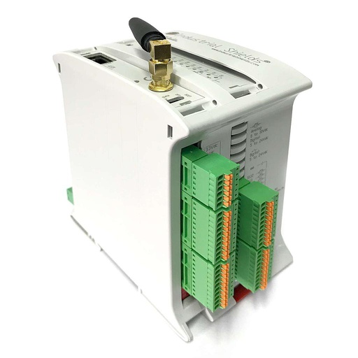
ESP32 PLC 21 FLEX
The case uses an ESP32 PLC and does not publish the model. The ESP32 PLC 21 FLEX fits the five parameters: 6 analog inputs, RS-485 for sensors with a digital interface, and an optional 4G board for a vehicle.
- Role in this case
- Reads the sensors of the fluid, checks the values and sends them to the monitoring system
- Processor
- ESP32 dual core, up to 240 MHz, 16 MB flash, 520 KB SRAM
- Inputs
- 13: 6 analog/digital (0-10 V, 11-bit) and 7 digital optoisolated, 5 to 24 Vdc, 2 with interrupt
- Outputs
- 8: 3 analog/digital/PWM (0-10 V, 12-bit) and 5 digital optoisolated, 5 to 24 Vdc
- Communications
- Ethernet 10/100, Wi-Fi 2.4 GHz, Bluetooth LE, RS-485, RS-232, I2C, SPI
- Power and options
- 12 to 24 Vdc, DIN rail TS35, IP20; one optional board: 4G LTE-M/NB-IoT, LoRa or CAN
The case does not publish the exact ESP32 PLC model. The image shows the ESP32 PLC 21 FLEX. A Pt100 or an amperometric sensor does not go straight to a 0-10 V input: it needs its transmitter. For more analog channels, the ESP32 PLC 42 has 12.
Questions about this case
What does smart fluid monitoring measure?
In this case, five parameters: pressure, temperature, level, quality and chemical composition. Pressure keeps the conditions safe, temperature keeps the fluid away from extremes, level keeps the right volume, quality checks the specifications and composition detects contamination. Other sensors, such as viscosity or compression, are added for each fluid.
How does a PLC read a Pt100 temperature sensor?
A Pt100 is a resistance that changes with temperature (100 Ω at 0 °C). The analog inputs of the ESP32 PLC measure 0 to 10 V, so the Pt100 goes through a transmitter that gives 4-20 mA or 0-10 V, and the program scales the reading to degrees.
What is an amperometric sensor?
An electrochemical sensor. It applies a voltage to an electrode and measures the current of the reaction, which is proportional to the concentration of a substance, such as dissolved oxygen or chlorine. It connects through its transmitter. The case uses Mettler Toledo amperometric sensors and does not publish what they measure.
How do you connect a 4-20 mA sensor to an ESP32 PLC?
Through a precision shunt on an analog input. With 500 Ω, 20 mA gives 10 V and 4 mA gives 2 V. The program scales 2 to 10 V to the range of the sensor. A current below 3.6 mA means a broken wire or a fault, not a zero (NAMUR NE 43).
Recurring status or alert: what is the difference?
A recurring status reports the condition of the fluid at a fixed interval, even when all is well. An alert goes out when a key indicator has an unexpected or alarming variation. A typical way to set it: a limit for the value and a limit for its rate of change.
Why does the dual core of the ESP32 help?
With the Arduino core for the ESP32, the program can run tasks on each core. One core can read the sensors and run the logic while the other handles Wi-Fi, Ethernet or 4G. The case says that processes and communications are managed separately, which improves capacity and speed.
Download the case study
4-page PDF with the challenge, the logic, the architecture and the hardware. No form required.
Monitoring a fluid in a tank or on the road?
Tell us the fluid and what must not change. An engineer will answer.
Tell us the fluid, the variables you need, the sensors you have, where the data must go and who gets the alerts. We will propose the PLC, the inputs and the link.
- You get an answer from our technical team
- PLC, inputs and link to your monitoring system
- Arduino, ESP32 or Raspberry Pi based PLCs