Introduction
It took Thomas A. Edison 1000 failures before he invented the light bulb. Now that we know how to do it, we are constantly looking for how to optimize processes. And that's what we've done at Industrial Shields®! We have created official Node-RED nodes to make it much easier for us to activate and deactivate the outputs of a Raspberry Pi PLC controller.
In this case, we will focus on digital outputs, so that you can turn LEDs on and off or whatever you want to connect!
Related Links
Node-RED Tutorial
Requirements
- Raspberry PLC
- Power Supply
- Either Ethernet or HDMI cable with an external screen to connect to your Raspberry Pi based PLC.
- Raspberry PLC Industrial Shields C++ Library configuration (Installation 1-7 steps)
- Node-RED-Dashboard Library
Installation
- Install Node-RED in your open source PLC Raspberry Pi, if it is not yet.
- Install the node-red-contrib-rpiplc-node nodes.
- In Node-RED, go to Menu - Manage palette - Install. And search for node-red-contrib-rpiplc-node.
- Follow the steps of this link.
Industrial Shields Nodes
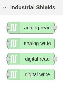
Once the nodes are successfully installed, you will be able to see the four nodes in the nodes section.

Digital Write Node
Now, we will use the digital write node, which is an output node for write the industrial Raspberry PLC digital output pins:
- Add the node to your flow.
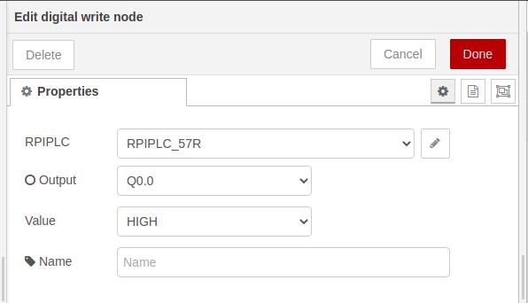
- Double-click and add a new industrial Raspberry Pi PLC configuration.
- Select the model of the Raspberry Pi industrial PLC.
- Click on Add.
- Select an output.
- Select a value and click on Done.
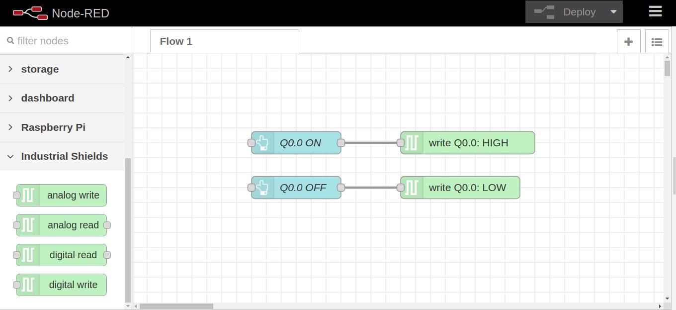
Optionally, in the value field of the digital write node editor, select -. And in the edit button node, change the option "When clicked, send" for the following payload:
- Numeric: 0 or 1.
- Boolean: true or false.
- String: HIGH or LOW.

Node-RED Flow
Now it is your turn! Copy the flows.json below, go to the Menu - Import - and paste the code! You will be able to play with the outputs!
[{"id":"f5e89d62.2ca78","type":"tab","label":"Flow 1","disabled":false,"info":""},{"id":"f4885305.c5c6","type":"ui_button","z":"f5e89d62.2ca78","name":"Q0.0 ON","group":"33d04b74.74e3e4","order":0,"width":0,"height":0,"passthru":false,"label":"ON","tooltip":"","color":"","bgcolor":"","icon":"","payload":"","payloadType":"str","topic":"topic","topicType":"msg","x":260,"y":140,"wires":[["aa7f7ce9.f7fb8"]]},{"id":"aa7f7ce9.f7fb8","type":"rpiplc-digital-write","z":"f5e89d62.2ca78","rpiplc":"42130fc3.e6fd1","pin":"Q0.0","value":"1","name":"","x":450,"y":140,"wires":[]},{"id":"8b00f56d.2d6bc8","type":"ui_button","z":"f5e89d62.2ca78","name":"Q0.0 OFF","group":"33d04b74.74e3e4","order":0,"width":0,"height":0,"passthru":false,"label":"OFF","tooltip":"","color":"","bgcolor":"","icon":"","payload":"","payloadType":"str","topic":"topic","topicType":"msg","x":260,"y":200,"wires":[["dff33a3c.a21828"]]},{"id":"dff33a3c.a21828","type":"rpiplc-digital-write","z":"f5e89d62.2ca78","rpiplc":"42130fc3.e6fd1","pin":"Q0.0","value":"0","name":"","x":440,"y":200,"wires":[]},{"id":"33d04b74.74e3e4","type":"ui_group","name":"Default","tab":"9882cc2c.3cb1d","order":1,"disp":false,"width":"6","collapse":false},{"id":"42130fc3.e6fd1","type":"rpiplc-config","model":"RPIPLC_57R","name":""},{"id":"9882cc2c.3cb1d","type":"ui_tab","name":"Home","icon":"dashboard","disabled":false,"hidden":false}]


Node-RED Tutorial: How to set digital outputs to Raspberry PLC